Today, we will continue discussing the construction elements used to build the facade cladding of large commercial buildings in DC. The combined series of from here last week’s and today’s articles follows:
a. Cast-in-place Concrete Structures b. Stone Panel Cladding Systems 3. Sealing and flashing details 4.Additional Design Considerations a. Structural loads (wind, seismic, dead loads) b. Thermal expansion and contraction c. Fire resistance and safety Sealing and Flashing DetailsThere are several sealing and waterproofing aspects of stone panel cladding systems in order to prevent water infiltration behind the panels. This is an interesting aspect of the overall system design options, as the stone panels themselves are not normally intended to be the primary weather barrier. Instead, the waterproofing and moisture management components are often located behind the panels, at the attachment points and interface with the building structure. 
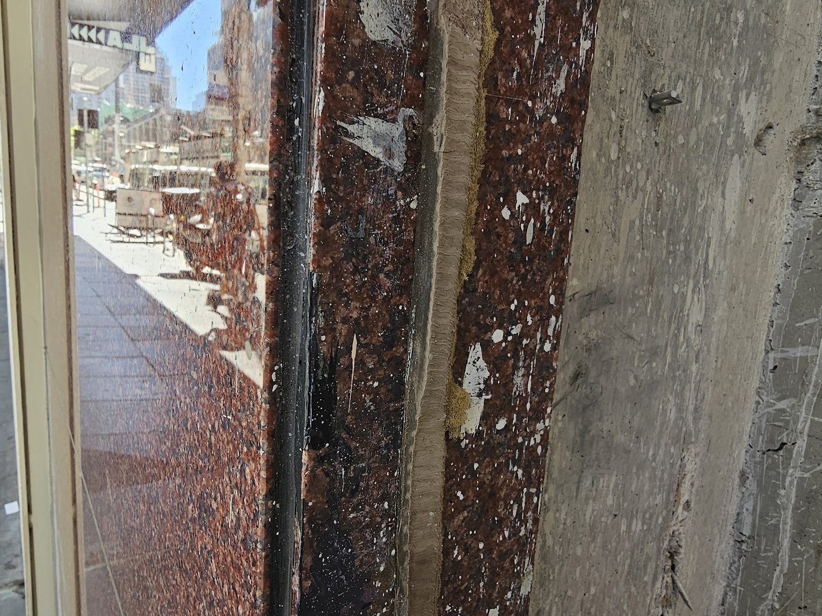
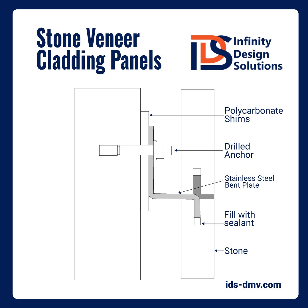
Behind the stone panels, a series of waterproofing materials and techniques are often used to create a continuous, watertight barrier. High-performance sealants and gaskets are applied around the mounting hardware meets the substrate wall system. These sealants are typically made from advanced polymer materials, such as silicone or polyurethane, which are specifically designed to withstand harsh environmental conditions, including UV exposure, temperature fluctuations, and moisture. They are able to remain flexible over time, accommodating the natural thermal expansion and contraction of the stone panels and metal framing without cracking or separating. At the interface between the stone panels and the framing system, these sealants are applied in a continuous bead or gasket, creating a weather-tight seal that prevents water from penetrating behind the panel. However, curtain walls work in a way that is often counterintuitive to most people. The vapor barrier is often built at the substrate wall, not at the exterior curtain wall.
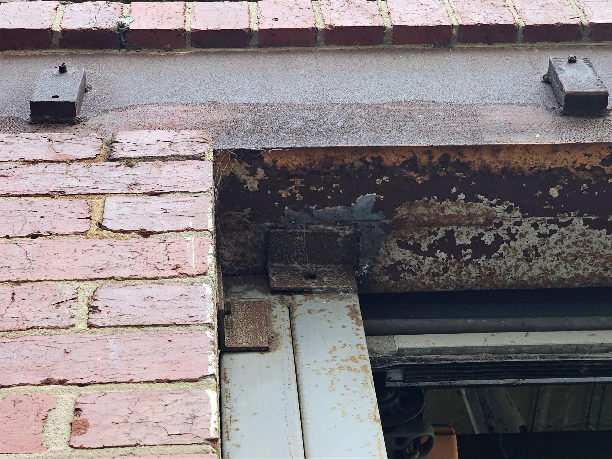
Flashing components, typically made from durable and weather resistant materials like stainless steel or aluminum, are also integrated into the system at critical transition points, such as corners, window openings, or where the cladding meets other building elements. These flashings help direct water away from vulnerable areas and prevent it from getting behind the stone panels. The attachment points where the metal framing or clips are secured to the primary building structure are also carefully sealed and waterproofed. This is typically achieved using a combination of gaskets, sealants, and self-adhered waterproofing membranes that form a continuous barrier around the penetrations. In many cases, an additional layer of waterproofing membrane or fluid-applied coating may be applied over the entire surface behind the stone panels, providing an extra level of protection against moisture intrusion. These membranes are carefully integrated with the other waterproofing components, such as sealants and flashings, to create a seamless and redundant moisture barrier. It’s important to note that the waterproofing and sealing systems used in stone panel cladding are not only designed to prevent water infiltration but often also to allow for proper drainage and ventilation. This helps prevent moisture from becoming trapped behind the panels, which could lead to potential issues such as mold growth or corrosion. By incorporating these various waterproofing materials and techniques, with proper installation practices, stone panel cladding systems largely manage moisture and prevent water infiltration behind the panels and into the building’s interior. This approach allows the stone panels to provide a durable exterior cladding, while the waterproofing components work in tandem to protect the building’s exterior shell. Additional Design ConsiderationsStructural loads (wind, seismic, dead loads) Structural loads, including wind, seismic, and dead loads, need to be considered and addressed in the design and installation of stone panel cladding systems. This is aspect must be evaluated to understand the performance of these systems, especially in high-rise buildings. Wind Loads: Stone panel cladding systems are exposed to significant wind forces, particularly in tall buildings and coastal regions. These wind loads can exert substantial pressures on the cladding, potentially causing deflection, vibration, or even failure if not fully analyzed. The design of the cladding system must consider the specific geographic wind speed data, building height, and specific site conditions to determine the appropriate wind load factors. The metal framing and attachment components must be to withstand these wind pressures, transferring the loads back to the primary building structure. The size, spacing, and connections of the framing members are calculated to resist the anticipated wind forces acting on the cladding surface area. Additionally, the panel-to-frame connections, typically utilizing specialized clips or anchors, are designed to securely hold the stone panels in place under wind load conditions. Seismic Loads: In regions prone to seismic activity, stone panel cladding systems must be designed to accommodate typical or expected lateral forces and movements associated with earthquakes. During seismic events, the building structure can experience significant horizontal accelerations and displacements, which can place substantial stresses on the cladding system. To mitigate these seismic loads, the cladding system is designed with a certain degree of flexibility and movement capability. The connections between the metal framing and the primary building structure often incorporate slotted holes or specialized sliding connections that allow for controlled movement during an earthquake. This helps prevent or reduce the transfer of excessive forces from the building to the cladding, reducing the risk of damage or failure. Additionally, the panel-to-frame connections are engineered to accommodate the anticipated inter-story drift, which is the relative horizontal displacement between adjacent floors during seismic activity. By allowing for this movement, the stone panels can remain securely attached while avoiding excessive stresses or cracking. Dead loads refer to the constant, static weight of the cladding system itself, including the stone panels, metal framing, and any additional components such as insulation or waterproofing layers. These loads are relatively straightforward to calculate based on the material densities and dimensions of the system components. The metal framing and its connections to the primary building structure must be designed to support the cumulative dead load of the entire cladding assembly, in addition to any imposed live loads or environmental loads. Proper load distribution and transfer through the framing system is critical to prevent excessive deflection or failure. In some cases, particularly for larger or heavier stone panel units, additional support components like shelf angles or gravity clips may be incorporated into the framing system to help distribute the dead load more effectively. To ensure the stone panel cladding system can withstand the various structural loads, comprehensive analysis and testing are typically performed during the design phase. This may include computer-aided structural modeling, finite element analysis, and physical testing of mock-up assemblies under simulated load conditions. Load tests may involve applying concentrated or distributed loads to the cladding system to evaluate its deflection, stress levels, and overall performance. These tests help validate the design assumptions and calculations, ensuring that the system meets or exceeds the required safety factors and building code requirements. Additionally, full-scale mock-ups may be constructed and subjected to simulated wind, seismic, or other environmental conditions to assess the overall system behavior and identify any potential weaknesses or areas for improvement. Mock-ups can be built by the contractor for additional cost but all of the design characteristics and evaluation should be analyzed by a third party engineer, not the contractor. Thermal expansion and contractionStone panel cladding systems are subject to the effects of thermal expansion and contraction due to fluctuations in temperature. This phenomenon occurs because materials expand when heated and contract when cooled at the molecular level. As temperatures rise, the atoms and molecules within a material gain kinetic energy and vibrate more, causing the material to increase in size. Conversely, when temperatures decrease, the reduced molecular vibrations allow the material to shrink back to its original dimensions. The degree to which a material expands or contracts per unit change in temperature is quantified by its coefficient of thermal expansion. Natural stone panels, such as granite, limestone, and slate, generally have relatively low coefficients of thermal expansion compared to other building materials. However, even small dimensional changes can accumulate over large surface areas or long lengths, potentially leading to significant movement within the cladding system. The metal framing components that support the stone panels, typically made of aluminum or steel, have higher coefficients of thermal expansion, meaning they may expand or contract at a different rate than the stone. This differential movement can create stress concentrations or undesirable separations between the materials. (In the series of three pictures above, you can see three images from a modern high-rise building, intact. The cladding goes up several stories above the ground and these particular panels are joined with an elastomeric sealant applied at the edges between panels.) To accommodate thermal movements, stone panel cladding systems incorporate several key design features. Expansion joints are strategically placed within the system, creating controlled separation points that allow adjacent panels or framing members to expand and contract independently without inducing excessive stress or cracking. The connections between the stone panels and metal framing are designed to be flexible, often utilizing specialized clips, anchors, or bracket systems that can accommodate differential thermal expansion. In regions prone to seismic activity, the cladding system must also accommodate seismic drift and inter-story movements during earthquakes. Slip connections or slotted holes in the framing attachments provide the necessary flexibility to prevent transferring excessive loads to the cladding components during these events. The sealants and gaskets used around the perimeter of the stone panels are carefully selected for their ability to remain flexible and maintain an effective seal even as the materials expand and contract. High-performance sealants with appropriate elongation capabilities are specified to accommodate the anticipated thermal movements. Proper consideration must be given to the selection and compatibility of stone panel and metal framing materials in terms of their thermal expansion coefficients. Materials with similar expansion rates help minimize differential movements and reduce the potential for stress concentrations or cracking. During the design phase, thermal analysis and computer modeling are often performed to simulate the anticipated thermal movements and optimize the placement of expansion joints, connection details, and other critical components. By incorporating these design strategies, stone panel cladding systems can effectively manage thermal expansion and contraction, maintaining structural integrity and weather-tight performance over time. The ability to accommodate dimensional changes due to temperature fluctuations is crucial for preventing potential failures, cracking, or premature degradation of the cladding system. Installers and construction teams, although not responsible for design, analysis and testing, must also follow installation procedures detailed by the designers to ensure that the thermal movement accommodations function as intended. This includes accurately spacing expansion joints, properly installing flexible connections and sealants, and adhering to manufacturer guidelines for material compatibility and thermal movement capacities. Overall, understanding and addressing thermal expansion and contraction is a consideration in the design, material selection, and installation of stone panel cladding systems. By accounting for these thermal movements, the cladding system can maintain its performance and aesthetic appeal, even when subjected to varying temperature conditions and thermal cycling throughout the service life. Fire Resistance of Stone Facade PanelsFrom an engineering perspective, fire resistance is a consideration for building cladding systems, particularly when it comes to historic brick masonry and exterior facades. Unlike traditional brick cladding, modern stone panel cladding systems offer similiar fire resistance capabilities, contributing to the overall safety and durability of a building’s exterior. Stone panels, such as granite, limestone, and slate, are inherently non-combustible materials that do not support combustion or contribute to the spread of fire. This characteristic makes stone panel cladding a choice for building facades, as it helps to contain and limit the propagation of fire. In contrast, historic brick masonry, while durable and long-lasting, can be more susceptible to fire damage. Bricks themselves are non-combustible, but the mortar joints between them, if not properly restored, tuckpointed or repointed, can be vulnerable to high temperatures, potentially leading to cracking, spalling, or even structural failure if exposed to prolonged or intense heat. The use of stone panel cladding systems can enhance the fire resistance of a building’s exterior by creating an additional layer of protection over the primary structural elements. The non-combustible nature of the stone panels acts as a barrier, preventing direct exposure of the underlying materials to flames or radiant heat. This can be particularly beneficial in high-rise buildings or densely populated urban areas, where the risk of fire spread between adjacent structures is a significant concern.
In contrast, stone panel cladding systems generally require less frequent and less intensive maintenance. The stone panels themselves are highly resistant to weathering, staining, and other environmental factors, requiring only occasional cleaning to maintain their appearance. The sealants and gaskets used in the cladding system may need to be inspected and replaced periodically, but this is typically a less extensive process compared to repointing or tuckpointing entire brick facades. It is important to note, however, that proper installation and detailing of stone panel cladding systems are crucial to ensuring their long-term performance and minimizing maintenance requirements. Poorly installed or improperly sealed systems can be susceptible to water infiltration, which can lead to staining, efflorescence, or even structural issues over time. We can HelpOur company focuses on historic restoration more than modern building upkeep, maintenance and construction, but our company understands both types of construction very well and a full picture well-rounded approach is needed in any niche in the construction industry. Although we focus on historic restoration, repointing, tuckpointing and historic brick repair, our company also has technical knowledge and competencies in the areas of modern and contemporary construction as well as we become one of the leaders in that area of the market today. Understanding both historic and modern or contemporary construction is useful because both aspects help understand the challenges and potential solutions for challenges in building science and construction. We can help with a variety of historic masonry restoration needs and upkeep, from modest tuckpointing and or repointing to complicated and extensive historic masonry restoration. Infinity Design Solutions is a historic restoration specialist contractor specializing in both historic masonry restoration such as tuck pointing our repointing, and brick repair. If you have questions about the architectural details or facade of your historic building in Washington DC, reach out and say hello and if we can help we’ll be glad to assist you. You can email us or call us on the telephone at the following link: contact us here. <p>The post Stone Veneer Cladding Panels – Part II of II first appeared on Infinity Design Solutions.</p> Via https://www.ids-dmv.com/masonry/stone-veneer-cladding-panels-part-ii-of-ii/
0 Comments
Whenever you’re in a downtown Urban area, like Washington DC or any modern cities, you generally see a variety of high-rise buildings with panel cladding. In some cases those panels are modern metals, but in other cases those panels are stone and the buildings look as if they are built with a structural stone facade. In many cases historic buildings will have a stone facade with stone masonry which relatively thick, but most modern buildings have a similar but different architectural aesthetic that looks more sleek and modern and the stone is not a thick heavy stone the way it is in historic buildings, instead it’s a thin panel being held on with metal clips. This is why many stone facade historic buildings, even large ashlar masonry stone buildings like churches, still need repointing, tuckpointing, and masonry restoration, but modern stone buildings, where buildings are built in a panelized system, do not need tuck pointing or repointing. If someone isn’t familiar with the construction process, they might be totally fooled into thinking the building is built with thick and heavy stone. However, that couldn’t be further from the truth. In fact the building is generally built with one of two primary main superstructure materials, either a relatively or comparatively lightweight structural steel frame or a comparatively somewhat lightweight cast in place concrete superstructure. Today, we will take a closer look at the construction elements used to build the facade cladding of buildings like this. The combined series, here today and this coming week’s articles, follows. Today we will discuss sections I. and II.:
2. Stone Panel Cladding Systems 3. Sealing and flashing details 4. Additional Design Considerations
Common Primary Building Structures in DCSteel Frame BuildingsSteel frame structures have become a popular choice for modern high-rise buildings due to their numerous advantages. One of the primary benefits of steel is its high strength-to-weight ratio, allowing for relatively lightweight yet incredibly strong structural frames. This property enables the construction of taller buildings with larger open floor plans, as the steel members can span greater distances while minimizing the need for additional interior columns or supports. Another advantage of steel frame construction is the speed at which it can be erected. Prefabricated steel components can be precisely manufactured off-site and then efficiently assembled on the construction site, reducing overall construction time and labor costs. This accelerated construction schedule can be particularly advantageous in urban areas where minimizing disruptions and meeting tight deadlines is crucial. However, despite its many advantages, steel frame structures also have some inherent limitations that must be acknowledged. One of the primary concerns is the susceptibility of steel to fire. When exposed to high temperatures, steel can lose a significant portion of its strength and stiffness, potentially leading to structural failure. To mitigate this risk, steel frames in buildings are typically encased in fire-resistant materials, such as concrete or specialized insulation, to provide protection during a fire event. Another limitation of steel frames is their vulnerability to corrosion, particularly in coastal or industrial environments where the air contains high levels of moisture and pollutants. Corrosion can weaken the steel over time, compromising its structural integrity. To combat this issue, steel members, where exposed, are often galvanized or coated with protective coatings, and proper maintenance and inspection protocols must be followed throughout the building’s lifespan. Despite these limitations, the advantages of steel frame structures, such as their strength, lightweight nature, and rapid construction, have made them a popular choice for modern high-rise buildings. However, careful design considerations, including fire protection measures and corrosion resistance strategies, are essential to ensure the long-term safety and durability of these structures. And despite the overall set of advantages, a critical threshold point is generally reached above 10 stories. At 10 stories or below, which is most common in Washington, DC, concrete superstructure buildings may be more cost effective. Cast-In-Place Post-Tensioned ConcreteThe popularity of post-tensioned concrete structures in Washington D.C. can be largely attributed to the city’s unique height restrictions for buildings. Since the late 19th century, a federal law has limited the height of structures in the city to ensure they do not overshadow or visually overwhelm some of the nation’s most iconic landmarks, such as the U.S. Capitol and the Washington Monument. The Height of Buildings Act of 1910 mandates that no building in Washington D.C. can exceed a height of 20 feet plus the width of the adjacent street or avenue it faces. This height limit effectively caps most buildings in the city to around 12 stories tall, with a few exceptions for taller structures in certain zoned areas. Post-tensioned concrete has become one of the preferred structural system for many of these mid-rise buildings in D.C. because of its inherent advantages within the imposed height constraints. The high strength and stiffness of post-tensioned concrete allow for longer span lengths and more open floor plans, maximizing the usable space within the limited building height. The fire resistance and thermal mass benefits of concrete make it an ideal choice for these mid-rise structures, enhancing safety and energy efficiency without the need for excessive height. The durability and longevity of concrete also align well with the historic and monumental nature of many buildings in the nation’s capital. In contrast, steel frame construction, while offering the potential for taller structures, may not be as advantageous for buildings restricted to lower heights. The additional height afforded by steel’s lightweight design is less relevant when height is capped by regulation. By using post-tensioned concrete as the primary structural system, architects and developers in Washington D.C. can optimize the design and functionality of their mid-rise buildings while respecting the city’s iconic skyline and historic height limitations. Post-tensioned concrete structures have gained popularity in modern high-rise construction due to their inherent durability and fire resistance. Unlike steel, which can lose its structural integrity when exposed to high temperatures, concrete is a non-combustible material that can withstand extreme heat without significant strength degradation. This fire-resistant property provides an added layer of safety and resilience for occupants in the event of a fire. Another advantage of post-tensioned concrete structures is their thermal mass. The dense concrete material has the ability to absorb and store heat energy, which can contribute to improved energy efficiency and thermal comfort within the building. This thermal mass effect can help regulate indoor temperatures, reducing the reliance on mechanical heating and cooling systems and potentially lowering energy costs over the building’s lifetime. Post-tensioned concrete structures offer durability and longevity. Concrete is highly resistant to environmental factors such as moisture, weathering, and corrosion, ensuring a long service life with minimal maintenance requirements. This durability can translate into lower long-term costs and a reduced environmental impact, making post-tensioned concrete an attractive choice for sustainable construction of mid-rise to high rise buildings in Washington, DC. However, one of the limitations of post-tensioned concrete structures is their heavier weight compared to steel frame buildings. The dense nature of concrete results in higher overall structural loads, which can necessitate more robust foundations and increased material usage. This additional weight can also pose challenges during construction, requiring specialized equipment and techniques for material handling and placement. Another limitation is the longer construction time often associated with post-tensioned concrete structures. Unlike prefabricated steel components, concrete structures typically require on-site formwork, reinforcement placement, and curing times. This process can be more labor-intensive and time-consuming, potentially leading to longer project durations and increased construction costs compared to steel frame buildings. Despite these limitations, the advantages of post-tensioned concrete structures, such as their fire resistance, thermal mass, and exceptional durability, make them a popular choice for modern high-rise buildings where safety, energy efficiency, and long-term performance are key priorities. Stone Cladding SystemsStone panels are the prominent feature of modern cladding systems, providing a specific aesthetic appeal and durability. A wide range of natural stone types can be used, including granite, limestone, slate, and quartzite, each offering unique colors, textures, and patterns. Engineered or reconstituted stone products are also available, offering consistent properties and potential cost savings. These stone panels are typically manufactured in somewhat standardized sizes ranging from 2 feet by 4 feet to 5 feet by 10 feet, with custom sizes also available for specific design requirements. A key advantage of modern stone panels is their thinness, typically ranging from 1 to 2 inches thick, making them significantly lighter and easier to handle compared to traditional thick, load-bearing stone facades. To support the stone panels, a metal framing system, commonly constructed from aluminum or galvanized steel components is applied to a curtain wall or applied frame. This framing consists of vertical mullions, horizontal rails, and various brackets and clips. The metal framing serves multiple crucial functions: providing a stable and adjustable mounting surface for the stone panels, accommodating thermal expansion and contraction movements, and transferring wind and gravitational loads back to the primary building structure. The specific configuration of the framing can vary, with some systems employing a grid-like pattern while others use a more minimalist approach with fewer visible elements. The metal framing that supports the stone panels is typically attached to the primary building structure using a variety of methods, depending on the specific system and building type. For steel frame structures, the framing may be anchored directly to the structural steel members using welded or bolted connections. In the case of concrete structures, the framing is often secured using cast-in-place anchors or post-installed anchors that are drilled and epoxied into the concrete. Once the primary metal framing is securely fastened to the building structure, specialized brackets and clips are used to attach the individual stone panels. These connections are designed to allow for slight movements and adjustments during installation, as well as to accommodate thermal expansion and contraction of the materials over time. In many systems, the stone panels are hung from the horizontal rails or brackets using metal clips or anchors that are secured into the back of the stone panels themselves. The anchors used to connect the stone panels to the framing are typically made of stainless steel or other corrosion-resistant materials. They may be secured to the stone using epoxy adhesives or mechanical anchors that are embedded into the stone during fabrication. The anchors are designed to distribute the loads evenly across the panel, preventing stress concentrations that could lead to cracking or failure. During installation, the stone panels are typically lifted and positioned using lifting equipment and rigging systems. Cranes or material lifts are often employed to hoist the panels into place, particularly for taller buildings or areas with limited access. To safely handle the heavy stone panels, suction cup lifters or specialized clamps are used, which grip the panels securely without causing damage. Once a panel is in position, it is guided onto the metal brackets or clips, with adjustments made as necessary to ensure proper alignment and a tight fit. Experienced installers use specialized tools and techniques to make minor adjustments to the panel positions, ensuring a uniform and visually appealing facade. Shims or spacers may be used to maintain consistent joint spacing between adjacent panels. A diagram showing a typical type of installation of a stone cladding system supported by aluminum clips follows below for reference. As the installation progresses, sealants and gaskets are, in some designs, applied around the perimeter of each stone panel to create a weather-tight barrier and accommodate any differential movement between the panel and framing system. These sealants are typically high-performance products designed to withstand UV exposure, temperature fluctuations, and other environmental factors. In addition to the primary stone panel installation, careful attention is paid to detailing around corners, transitions, and other interfaces to ensure a continuous and seamless appearance. Flashing and trim components may be integrated to provide a finished look and prevent water infiltration at these critical areas. Throughout the installation process, quality control measures are implemented to ensure compliance with project specifications and building codes. This may include inspections, testing of anchors and connections, and verification of proper sealant application and joint dimensions. In addition to the stone panels and metal framing, stone panel cladding systems can be laid concealing or covering layers of insulation and waterproofing materials to enhance the building’s thermal performance and prevent moisture infiltration. These layers are installed between the stone panels and the primary building structure, creating a continuous thermal and moisture barrier. The insulation layer, often composed of rigid foam board or mineral wool, helps improve energy efficiency by reducing heat transfer through the facade. Waterproofing layers, such as self-adhered membranes or fluid-applied coatings, are critical components that prevent moisture from penetrating the facade and reaching the building’s interior. Proper integration and installation of these waterproofing layers are essential to prevent water damage, mold growth, and other moisture-related issues. In some cases, additional components such as air and vapor barriers, fire-resistant materials, and drainage systems may be incorporated to further enhance the cladding system’s performance and meet specific building code requirements. The combination of carefully selected stone panels, engineered metal framing, insulation, and waterproofing layers creates a high-performance cladding system that not only provides a visually stunning exterior but also contributes to the overall energy efficiency, durability, and longevity of the building. Attention to detail in the design, material selection, and installation of these components is crucial for ensuring the long-term success and integrity of the stone panel cladding system. We can HelpOur company focuses on historic restoration more than modern building upkeep, maintenance and construction, but our company understands both types of construction very well and a full picture well-rounded approach is needed in any niche in the construction industry. Although we focus on historic restoration, repointing, tuckpointing and historic brick repair, our company also has technical knowledge and competencies in the areas of modern and contemporary construction as well as we become one of the leaders in that area of the market today. Understanding both historic and modern or contemporary construction is useful because both aspects help understand the challenges and potential solutions for challenges in building science and construction. We can help with a variety of historic masonry restoration needs and upkeep, from modest tuckpointing and or repointing to complicated and extensive historic masonry restoration. Infinity Design Solutions is a historic restoration specialist contractor specializing in both historic masonry restoration such as tuck pointing our repointing, and brick repair. If you have questions about the architectural details or facade of your historic building in Washington DC, reach out and say hello and if we can help we’ll be glad to assist you. You can email us or call us on the telephone at the following link: contact us here. <p>The post Stone Veneer Cladding Panels – Part I of II first appeared on Infinity Design Solutions.</p> Via https://www.ids-dmv.com/masonry/stone-veneer-cladding-panels-part-i-of-ii/
This past week we took a look at several different types of heavy steel girders and lintels installed in historic masonry buildings to create large structural openings. Today, we will continue looking at the similar aspects of this topic with a focus on some of the structural engineering used in the evolution of brick masonry.
Last week’s topics:
Topics covered in the today’s article:
Tensile Strength of Masonry Tensile strength refers to a material’s ability to withstand forces that pull it apart or stretch it. In the case of brick and masonry, tensile strength is generally relatively low compared to their compressive strength, which is their ability to resist forces that tend to crush or compress them.
The reason brick and masonry have low tensile strength is due to their composition and the way they are constructed. Bricks are made from clay or shale that is fired at high temperatures, creating a porous and brittle material. While this process gives bricks excellent compressive strength, it also makes them vulnerable to tensile forces.
When a tensile force is applied to brick or masonry, it tries to pull the individual bricks or units apart. However, the mortar that holds the bricks together has limited tensile strength and can only resist a small amount of tension before cracking or separating from the bricks. Once the mortar bond is broken, the bricks themselves have little inherent ability to resist tensile forces, and they can easily separate and fail.
Additionally, bricks and masonry units often have microscopic cracks or imperfections that can act as stress concentrators, amplifying the effects of tensile forces and leading to premature failure. These imperfections can be caused by the manufacturing process, environmental exposure, or even the weight of the masonry itself.
In this scenario, the imposed load on a header, such as a steel lintel or reinforced concrete beam, is primarily from the brickwork directly above the opening in the triangular pattern. The header is designed to span the opening and transfer the weight of this corbelled arch to the adjacent wall sections or support structures, effectively resisting the tensile forces that the masonry cannot withstand on its own.
It’s important to note that while the corbelled arch can provide some support for the masonry above an opening, it is still always recommended to use proper structural headers, especially in larger openings or when the loads are significant. The corbelled arch can help distribute the loads, but it is not a substitute for a properly designed and installed header system that can effectively resist the tensile forces and ensure the long-term stability of the masonry construction. (Even in the case if a corbelled opening, a door or window would not be necessarily, in fact rarely if ever, built to fit the rough shape of a corbelled opening. Therefore the interstitial masonry would at least need to be supported, and in a large opening, that load could be massive.) Compressive Strength in Structural SupportMasonry materials, such as bricks, blocks, and stones, possess inherently high compressive strength due to their composition and manufacturing processes. This characteristic makes them well-suited for structural applications where resistance to compressive forces is crucial. Bricks are made from clay or shale that is molded and fired at high temperatures, resulting in a dense, hard, and durable material. The firing process fuses the clay particles together, creating a strong, crystalline structure that can withstand substantial compressive loads. The compressive strength of bricks typically ranges from 10 MPa to 100 MPa, depending on the type, quality, and manufacturing method. Similarly, concrete blocks and natural stones, such as limestone or granite, exhibit high compressive strength due to their dense and tightly-packed internal structure. Concrete blocks are made by compacting a mixture of cement, aggregates, and water, which hardens over time and develops a strong, rigid matrix. Natural stones are formed through geological processes that involve extreme heat and pressure, resulting in highly dense and crystalline structures. The compressive strength of masonry materials is derived from their ability to resist deformation and fracture under compressive loads. When a compressive force is applied, the individual particles or grains within the material are compressed and held together by internal cohesive forces. This internal structure allows the material to distribute the compressive load evenly, preventing localized failure or crushing. In contrast, materials like gypsum and wood have relatively low compressive strength due to their inherent properties and structural composition. For comparison, gypsum, a soft, mineral-based material, is primarily used for non-structural applications, such as drywall and plaster. Its crystalline structure is less dense and more porous compared to masonry materials, making it susceptible to crushing under high compressive loads. Wood, a natural material composed of cellulose fibers, has excellent tensile and flexural strength but relatively low compressive strength perpendicular to the grain direction. Wood is an anisotropic material, meaning its properties vary depending on the direction of the applied load. (**As a side note, we will have another article coming out isotropic vs. anisotropic materials coming out in the next two months.) When compressed parallel to the grain, wood can withstand higher loads due to the alignment of its fibers. However, when compressed perpendicular to the grain, the fibers can buckle or crush more easily, resulting in lower compressive strength. The high compressive strength of masonry materials is a fundamental reason why they have been used extensively in structural applications throughout history, particularly in load-bearing walls, columns, and foundations. Their ability to resist compressive forces ensures the structural stability and durability of masonry constructions, making them well-suited for historic restoration and preservation projects. I-Beams vs. Steel AnglesThe shape and configuration of steel support materials play a direct role in determining its load-bearing capacity and rigidity. A flat bar of steel, while strong in tension and compression along its length, lacks the necessary stiffness to resist lateral forces or bending moments when loaded from above, in a flat position. By comparison though, shapes like I-beams and steel angles can be exponentially stronger, providing rigidity and load-bearing capacity through their geometric configurations. A flat bar of steel, when loaded with weight or mass from above, can easily deflect or buckle due to the lack of sufficient moment of inertia. Moment of inertia is a measure of a structural member’s resistance to bending or twisting, and it is directly related to the shape and distribution of material within the cross-section. A flat bar, with its material concentrated along a single axis, has a relatively low moment of inertia, resulting in poor rigidity and susceptibility to lateral deformation under load. However, when straight pieces of steel are interconnected at angles, forming shapes like I-beams or double steel angles, they gain significant rigidity and resistance to bending and lateral deformation. This is achieved through the strategic positioning of the material away from the neutral axis, increasing the moment of inertia and consequently enhancing the overall stiffness of the member. In the case of an I-beam, the flanges at the top and bottom, connected by a web, create a highly efficient cross-sectional shape that maximizes the moment of inertia. The flanges resist the compressive and tensile forces, while the web resists shear forces, resulting in a lightweight yet significantly strong and rigid member capable of spanning long distances and supporting substantial loads. Similarly, double steel angles, formed by positioning, without even a physical connection such as welding or bolting two angle sections back-to-back, create a sturdy and rigid structural member. The alternating directions of the angles provide resistance to bending in multiple directions, while the interconnected configuration increases the overall moment of inertia and stiffness. Both I-beams and double steel angles can be used as girders or headers in masonry openings, such as door or window lintels. In these applications, they span across the opening and transfer the loads from the masonry above to the supporting elements on either side. The calculation of the bearing load resistance in a header configuration involves analyzing the combined effects of bending, shear, and axial forces acting on the member. The principles of structural mechanics are applied to determine the maximum allowable loads based on factors such as the material properties, cross-sectional dimensions, span length, and support conditions. Key calculations include determining the maximum bending moment and shear force acting on the member, calculating the section modulus and shear area to ensure adequate resistance to bending and shear stresses, and verifying the axial load capacity based on the compressive or tensile strength of the material. Additionally, deflection criteria may be considered to ensure the header does not experience excessive deformation under service loads, which could potentially compromise the integrity of the masonry above or cause functional issues with the opening. Brick Maintenance and Concerns at I-Beams and Steel AnglesWhen combining brick masonry and steel structural members, such as I-beams or steel angles, there are specific maintenance concerns and challenges that arise due to the inherent material incompatibilities. Although these materials can be integrated into a single construction system / assembly, they do not naturally bond well to one another, leading to potential separation and durability issues. One of the primary concerns is the lack of a strong adhesive bond between brick (mortar) and steel. Bricks are typically set using mortar, which forms a strong bond with the porous surface of the masonry units. However, the smooth surface of steel does not allow for effective mechanical or chemical bonding with the mortar, resulting in a weak interface and potential separation over time. At steel angle locations, bricks are generally set on top of the bottom leg of the angle, leaving the upper leg embedded within the brickwork. While this configuration conceals a portion of the steel angle, it also creates a potential path for moisture infiltration between the brick and steel surfaces, leading to accelerated deterioration, due to the occurrence of separation and delamination. In contrast, when using I-beams as lintels or support members, the bricks are often set directly on top of the top flange. However, at the sides, both the top and bottom flanges must be embedded within the brickwork to ensure proper load transfer and stability. This configuration presents additional challenges in maintaining a durable and moisture-resistant interface between the brick and steel surfaces. Regardless of the steel member used (angle or I-beam), where bricks are set around the flanges or legs, regular mortar alone is not sufficient to ensure a long-lasting and durable installation. Regular mortar, when not fully embedded into the bed joints, can delaminate easily, leading to separation and potential structural issues. To address this concern, elastomeric sealants are often applied at the interfaces between the brick and steel members. These sealants are designed to accommodate movement and maintain a flexible, waterproof barrier, preventing moisture penetration and subsequent deterioration of the steel components. Proper sealing is crucial because steel members embedded within masonry are more susceptible to accelerated moisture exposure, which can lead to oxidation and eventual failure. Even with protective coatings, the presence of moisture can compromise the steel’s integrity over time, potentially compromising the structural performance of the entire assembly. Maintenance and inspection programs are essential for historic masonry structures incorporating steel members. Regular monitoring for signs of separation, cracking, or moisture intrusion at the brick-steel interfaces should be conducted. Reapplication of sealants or repair of damaged areas may be necessary to ensure the long-term durability and integrity of the structure. Additionally, measures to control moisture levels within the masonry assembly, such as proper drainage and ventilation, can help mitigate the risk of accelerated steel deterioration. We can HelpWe can help with a variety of historic masonry restoration needs and upkeep, from modest tuckpointing and or repointing to complicated and extensive historic masonry restoration. Infinity Design Solutions is a historic restoration specialist contractor specializing in both historic masonry restoration such as tuck pointing our repointing, and brick repair. If you have questions about the architectural details or facade of your historic building in Washington DC, reach out and say hello and if we can help we’ll be glad to assist you. You can email us or call us on the telephone at the following link: contact us here. <p>The post Heavy Steel and Iron Girders Carrying Brick Masonry – Part II of II first appeared on Infinity Design Solutions.</p> Via https://www.ids-dmv.com/masonry/heavy-steel-and-iron-girders-carrying-brick-masonry-part-ii-of-ii/ Masonry and brick construction has been used throughout the world for thousands of years even in remote parts of the world where there have been no interchange or exchange between various disparate peoples. The occurrence of science or technology being invented by people with no cross pollination between them is a phenomenon known as multiple invention or parallel invention. This phenomenon has happened many times in the history of human existence, but few occurrences of multiple invention have propelled civilization forward as mush as brick masonry. Brick masonry has allowed humans to build structures and stable, safe housing in close proximity in cities throughout the world over millennia. Steel hasn’t always been used as a component in brick masonry, but in contemporary structures and in the late historic structures still found in our modern cities, steel has allowed openings for doors, windows gated and even carports and roadways. Today we will discuss halow steel lintels are used to support brick opening headers. The overall outline of a two-part perishes on the topic follows below. The items highlighted below will be discussed in today’s article and then the items below that will be discussed in the article this coming week. This week’s topics:
Topics covered in the next article:
Supporting Masonry with a HeaderMasonry construction, particularly in historic buildings, requires careful consideration of structural support systems to ensure the longevity and stability of the structure. One crucial element in this regard is the use of structural headers above openings such as doors, windows, and arches. A header, in the context of masonry construction, refers to a structural member that spans across an opening and supports the weight of the masonry above it. Without a proper header in place, the weight of the masonry would cause the opening to collapse inward, compromising the structural integrity of the entire wall assembly. The need for structural headers arises from the inherent nature of masonry materials like bricks or stone blocks. While these materials possess excellent compressive strength, their tensile strength (resistance to being pulled apart) is relatively low. When an opening is introduced in a masonry wall, the weight of the masonry above the opening creates tensile forces that the bricks or stones alone cannot effectively resist. Structural headers are designed to bridge the opening and transfer the weight of the masonry above to the adjacent wall sections or support structures. By distributing the load evenly, headers prevent the masonry from failing under its own weight and maintain the structural stability of the wall assembly. (The picture above shows a common horizontal steel lintel set on top of a brick wall at the side of an opening.) In historic masonry construction, headers were often made of materials such as wood beams or steel lintels. These structural elements were carefully integrated into the masonry during the construction process, ensuring that they were properly supported and capable of bearing the imposed loads. Over time, as construction techniques evolved and the understanding of structural engineering advanced, various types of headers were introduced to meet the demands of different building styles and load requirements. Modern masonry construction often employs steel lintels, reinforced concrete beams, or pre-engineered structural components as headers, offering enhanced strength and durability. Regardless of the specific material used, the proper installation and maintenance of structural headers are crucial in preserving the integrity of historic masonry structures. Failure or deterioration of these crucial elements can lead to cracking, bulging, or even collapse of the masonry above the opening, posing significant safety risks and potential damage to the building. (In the picture above you can see that the steel lintel supports the brick above by transferring the load to the side walls.) Historic Arches used TodayBrick masonry, while known for its durability and compressive strength, is inherently weak in resisting tensile forces. When an opening, such as a door or window, is introduced in a brick wall, the weight of the masonry above the opening creates horizontal tensile forces that the bricks alone cannot withstand effectively. Without a proper structural support system, such as an arch or a horizontal lintel header, the bricks above the opening will eventually succumb to these tensile forces, leading to collapse and failure. The reason for this vulnerability lies in the nature of brick construction itself. Bricks are laid in a staggered pattern, with each brick overlapping the one below it and held together by mortar. While this arrangement provides excellent compressive strength, allowing the bricks to transfer the load vertically, it lacks the ability to resist horizontal tensile forces effectively. When an opening is present, the bricks above it no longer have continuous vertical support, creating a gap or discontinuity in the load transfer path. As gravity acts on the weight of the masonry above the opening, it generates horizontal tensile forces that pull the bricks outward and downward. Without a supporting structure to resist these forces, the bricks will eventually separate from one another, leading to cracking, bulging, and ultimately, collapse. (The steel lintel is connected to a vertical steel support but that still support actually was originally built as a frame for a roll-up door, not an original structural element.) An arch is a structural element that addresses this issue by transferring the weight of the masonry above the opening through a curved, self-supporting configuration. The bricks in an arch are arranged in a semicircular or segmental pattern, with each brick partially supporting the ones above it through compressive forces. This arrangement allows the weight of the masonry to be distributed evenly along the curve of the arch, effectively transferring the load to the adjacent wall sections or support structures. However, in situations where an arch is not feasible or desired, a horizontal lintel header becomes the primary support system for the masonry above the opening. A lintel header is a structural beam, typically made of steel, reinforced concrete, or wood, that spans across the opening and transfers the weight of the masonry above it to the adjacent wall sections or support structures. The lintel header functions by resisting the horizontal tensile forces generated by the weight of the masonry above the opening. Its strength and rigidity allow it to span the opening without deflecting or sagging, effectively distributing the load evenly to the supporting wall sections. Without a lintel header in place, the bricks above the opening would eventually succumb to the tensile forces, leading to cracking, bulging, and potentially catastrophic collapse. (The abandoned steel roll up door is now defunct but left in place and replaced with corrugated panels as a makeshift cheap alternative. This is a lot about the changing economic values of urban industrial space.) The Advent of Structural Steel and Steel HeadersThe advent of structural steel and the introduction of steel headers revolutionized the way masonry structures were built, allowing for greater spans, taller constructions, and more flexible designs. Although iron and steel have been around for centuries, their widespread use in construction as structural members is a relatively recent development. It wasn’t until the late 18th and early 19th centuries that the mass production of wrought iron and, later, steel became feasible. The Industrial Revolution and the advancement of manufacturing processes, such as the Bessemer process for steel production, paved the way for the widespread availability of these materials. Prior to the mass production of structural steel, masonry openings were primarily supported by wooden lintels or arched configurations. While these traditional methods were effective for smaller openings and lower loads, they imposed limitations on the size and design of buildings. Wooden lintels had limited span capabilities, and arches required specific structural configurations that could be limiting in certain architectural styles. The introduction of steel angles and I-beams as headers in masonry construction marked a significant turning point. These structural members could be mass-produced with consistent quality and strength, making them readily available for construction projects. Steel’s high strength-to-weight ratio and ductility allowed for longer spans and the ability to support greater loads compared to traditional materials like wood or cast iron. (Overall, the opening is very wide, a total span that would have been very difficult to accomplish with historic brick arches from just a few decades earlier.) Steel headers, whether in the form of angles or I-beams, could span across openings with minimal deflection, effectively transferring the weight of the masonry above to the supporting wall sections. This capability opened up new possibilities for builders, enabling the design of larger openings, taller structures, and more complex masonry configurations. The use of steel headers also facilitated the integration of other structural elements, such as reinforced concrete and steel framing systems, into masonry construction. This combination of materials allowed for greater flexibility in design, enabling the construction of buildings that were previously impractical using traditional masonry techniques alone. The mass production of steel also made it an economical choice for construction projects, making it accessible to a wider range of builders and developers. This accessibility, coupled with the material’s strength and durability, contributed to the widespread adoption of steel headers in masonry construction throughout the late 19th and early 20th centuries. (In an alleyway of this type, it’s important for vehicles to be able to enter into this type of facility, but the opening could not be as easily created without a steel support element.) The Imposed Load of Masonry HeadersMasonry headers, such as steel lintels or reinforced concrete beams, play a crucial role in supporting the weight of the masonry above openings in walls. While bricks are capable of withstanding significant compressive forces when stacked vertically, they lack the inherent tensile strength and bonding capacity to remain indefinitely suspended in a horizontal or arched configuration without proper support. Bricks are typically held together by mortar, a cementitious material that acts as a binding agent between the individual units. However, mortar itself possesses relatively low tensile strength compared to its compressive strength. Over time, the mortar can deteriorate due to various factors, such as environmental exposure, moisture intrusion, or thermal cycles, leading to a gradual weakening of the bond between the bricks. Even with a perfect mortar installation, there is an inherent limitation to the adhesive strength and cohesive bonding capacity of the mortar itself. Unlike resilient materials like elastomeric sealants or structural adhesives, mortar lacks the necessary flexibility and tensile strength to reliably hold the bricks together in a suspended or unsupported configuration for an extended period. (The picture above shows a massive vertical portion of a building supported by a single element of steel above this side of the passageway of the opening.) When bricks are stacked vertically, the weight of the masonry above is transferred through compressive forces, which the bricks can effectively withstand. However, in a horizontal configuration above an opening, the weight of the masonry creates tensile forces that pull the bricks apart. Without a supporting structure like an arch or lintel, these tensile forces will eventually overcome the limited bonding strength of the mortar, leading to separation and potential collapse of the masonry above the opening. Brick and mortar assemblies are designed to primarily resist compressive forces, not tensile forces. The inherent properties of these materials make them well-suited for load-bearing walls and structures where the weight is transferred vertically, but they lack the necessary tensile strength and cohesive bonding to remain indefinitely suspended or unsupported in a horizontal configuration. To address this limitation, structural headers like lintels or arches are introduced above openings in masonry walls. These elements are designed to transfer the weight of the masonry above the opening to the adjacent wall sections or support structures, effectively resisting the tensile forces and preventing the bricks from separating and collapsing. Arches accomplish this by distributing the load through compressive forces along their curved shape, while lintels or beams span the opening and resist the tensile forces through their inherent strength and rigidity. By providing this crucial support system, structural headers ensure the long-term stability and integrity of masonry constructions, preventing the potential failure and collapse that could occur if the bricks were left unsupported above an opening. We can HelpWe can help with a variety of historic masonry restoration needs and upkeep, from modest tuckpointing and or repointing to complicated and extensive historic masonry restoration. Infinity Design Solutions is a historic restoration specialist contractor specializing in both historic masonry restoration such as tuck pointing our repointing, and brick repair. If you have questions about the architectural details or facade of your historic building in Washington DC, reach out and say hello and if we can help, we’ll be glad to assist you. You can email us or call us on the telephone at the following link: contact us here. <p>The post Heavy Steel and Iron Girders Carrying Brick Masonry – Part I of II first appeared on Infinity Design Solutions.</p> Via https://www.ids-dmv.com/masonry/heavy-steel-and-iron-girders-carrying-brick-masonry-part-i-of-ii/ Masonry groin vault ceilings, known for their architectural elegance and structural ingenuity, have a rich history dating back to ancient civilizations. These ceilings are characterized by their intersecting barrel vaults, creating a ribbed or groined effect. Found in various architectural styles and structures worldwide, groin vaults have evolved over time, influenced by cultural, technological, and artistic advancements.
The origins of groin vault ceilings can be traced back to ancient Roman and Byzantine architecture, where they were used extensively in public buildings, temples, and cathedrals. The Romans perfected the technique of constructing vaulted ceilings using concrete and brick, allowing for larger and more elaborate structures. Byzantine architects further refined the design, incorporating decorative elements such as mosaic tiles and intricate patterns. During the Gothic period in Europe, groin vaults became a hallmark of cathedral architecture, with soaring ceilings and intricate ribbed designs symbolizing spiritual transcendence. Stonemasons built these vaults using locally sourced materials, such as limestone or sandstone, showcasing their craftsmanship and architectural prowess. In Renaissance and Baroque architecture, groin vaults continued to be used in palaces, churches, and public buildings, often embellished with decorative plasterwork, frescoes, and sculptures. The advent of new construction techniques and materials, such as reinforced concrete and steel, allowed for greater flexibility in vault design and construction. Anatomy and ComponentsA groin vault ceiling consists of two intersecting barrel vaults, creating a ribbed or groined structure. The ribs serve as load-bearing elements, transferring the weight of the ceiling to supporting walls or columns. Key components of a groin vault include: Ribs: Structural elements that define the groined pattern of the ceiling. Ribs can be made of stone, brick, concrete, or steel, depending on the architectural style and structural requirements.
Keystone: The central, wedge-shaped stone at the crown of the vault that locks the voussoirs in place and distributes the weight of the ceiling evenly. Springing Point: The point where the ribs of the groin vault meet the supporting walls or columns. This is where the load of the vault is transferred to the underlying structure. Spandrels: The triangular spaces between the ribs of the vault, often filled with decorative plasterwork, sculptures, or paintings. Famous Examples: Numerous historic buildings around the world feature magnificent groin vault ceilings, showcasing the architectural and artistic achievements of their respective eras. Some noteworthy examples include: Hagia Sophia (Istanbul, Turkey): Built in the 6th century, the Hagia Sophia boasts a grand groin vault ceiling adorned with intricate mosaics and calligraphic inscriptions. Chartres Cathedral (Chartres, France): A masterpiece of French Gothic architecture, Chartres Cathedral features a series of stunning groin vaults embellished with stained glass windows depicting biblical scenes. Palazzo Vecchio (Florence, Italy): This Renaissance palace features a magnificent groin vault ceiling in its Hall of the Five Hundred, adorned with elaborate frescoes by renowned artists such as Leonardo da Vinci and Michelangelo. Alhambra Palace (Granada, Spain): The Moorish palace complex of Alhambra showcases intricate muqarnas vaulting, a type of ornamental groin vault characteristic of Islamic architecture. Sainte-Chapelle (Paris, France): Known for its stunning stained glass windows and ribbed groin vaults, Sainte-Chapelle is a masterpiece of French Gothic architecture.
|
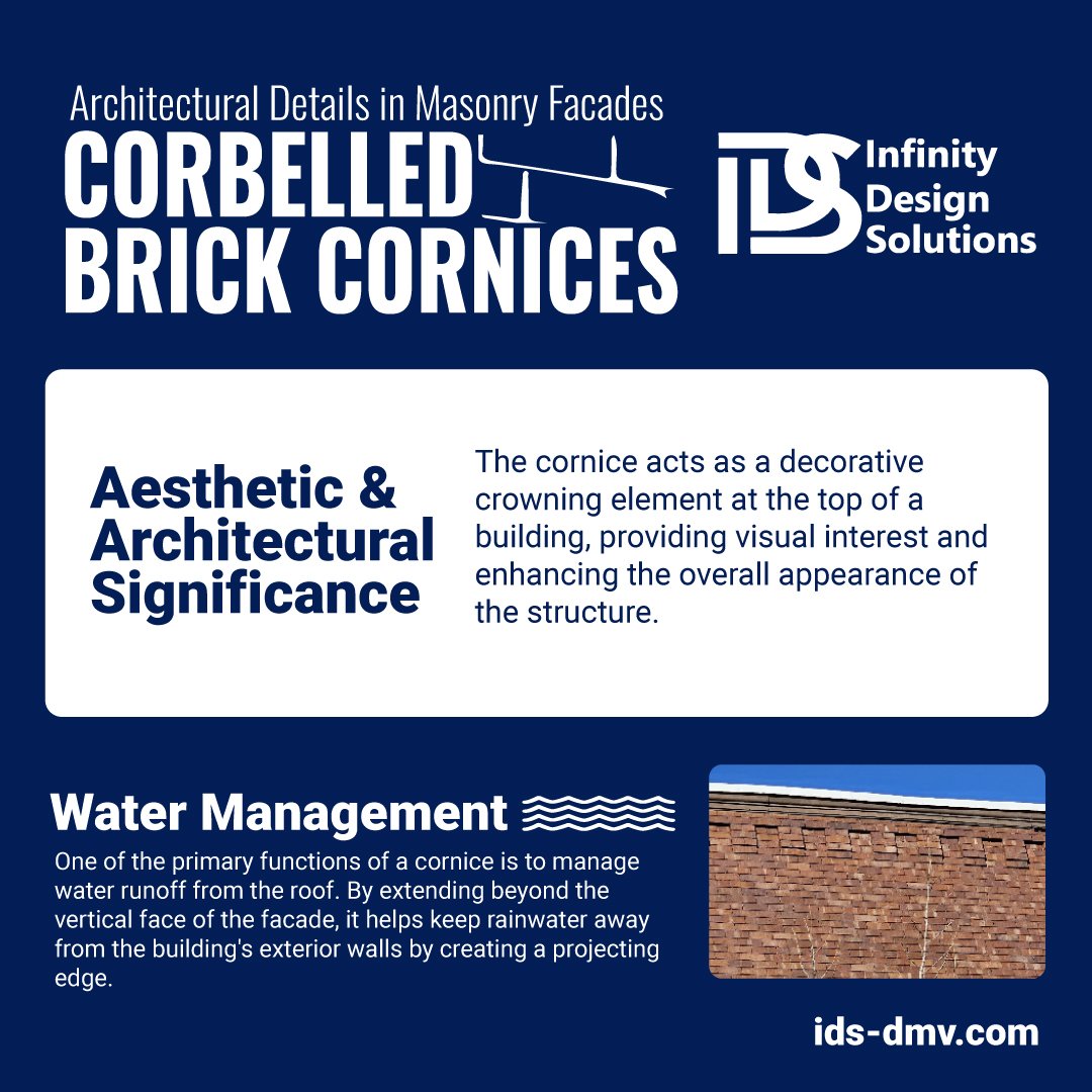
About UsInfinity Design Solutions LLC (IDS) is a full service general contracting company in the heart of the Dupont Circle neighborhood of Washington, DC. We focus on repair and renovation of buildings and facilities in both historic designated neighborhoods and the commercial-zoned central business district of the city. Follow Us
|