|
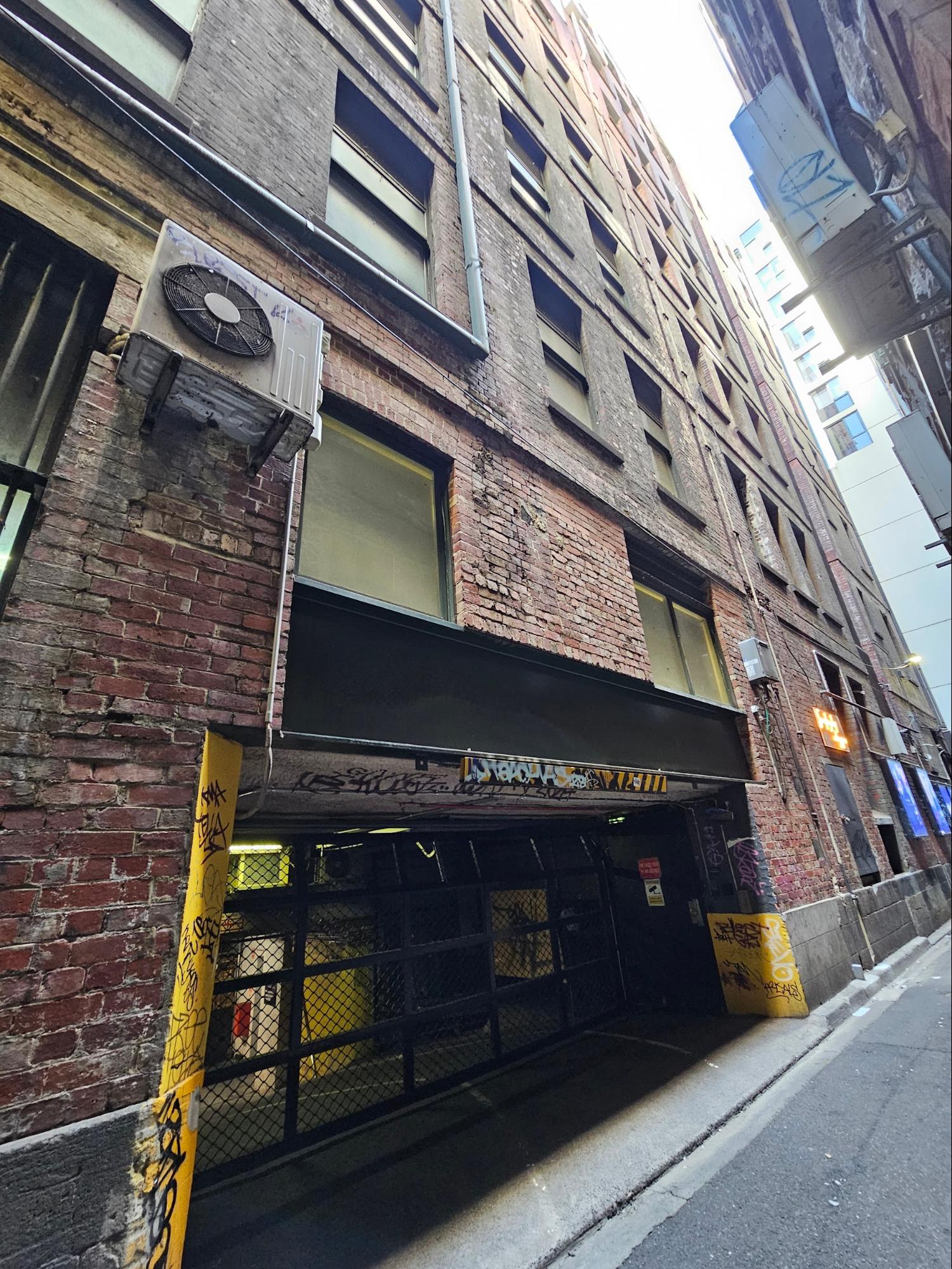
This past week we took a look at several different types of heavy steel girders and lintels installed in historic masonry buildings to create large structural openings. Today, we will continue looking at the similar aspects of this topic with a focus on some of the structural engineering used in the evolution of brick masonry.
Last week’s topics:
Topics covered in the today’s article:
Tensile Strength of Masonry Tensile strength refers to a material’s ability to withstand forces that pull it apart or stretch it. In the case of brick and masonry, tensile strength is generally relatively low compared to their compressive strength, which is their ability to resist forces that tend to crush or compress them.
The reason brick and masonry have low tensile strength is due to their composition and the way they are constructed. Bricks are made from clay or shale that is fired at high temperatures, creating a porous and brittle material. While this process gives bricks excellent compressive strength, it also makes them vulnerable to tensile forces.
When a tensile force is applied to brick or masonry, it tries to pull the individual bricks or units apart. However, the mortar that holds the bricks together has limited tensile strength and can only resist a small amount of tension before cracking or separating from the bricks. Once the mortar bond is broken, the bricks themselves have little inherent ability to resist tensile forces, and they can easily separate and fail.
Additionally, bricks and masonry units often have microscopic cracks or imperfections that can act as stress concentrators, amplifying the effects of tensile forces and leading to premature failure. These imperfections can be caused by the manufacturing process, environmental exposure, or even the weight of the masonry itself.
In this scenario, the imposed load on a header, such as a steel lintel or reinforced concrete beam, is primarily from the brickwork directly above the opening in the triangular pattern. The header is designed to span the opening and transfer the weight of this corbelled arch to the adjacent wall sections or support structures, effectively resisting the tensile forces that the masonry cannot withstand on its own.
It’s important to note that while the corbelled arch can provide some support for the masonry above an opening, it is still always recommended to use proper structural headers, especially in larger openings or when the loads are significant. The corbelled arch can help distribute the loads, but it is not a substitute for a properly designed and installed header system that can effectively resist the tensile forces and ensure the long-term stability of the masonry construction. (Even in the case if a corbelled opening, a door or window would not be necessarily, in fact rarely if ever, built to fit the rough shape of a corbelled opening. Therefore the interstitial masonry would at least need to be supported, and in a large opening, that load could be massive.)
Compressive Strength in Structural SupportMasonry materials, such as bricks, blocks, and stones, possess inherently high compressive strength due to their composition and manufacturing processes. This characteristic makes them well-suited for structural applications where resistance to compressive forces is crucial. Bricks are made from clay or shale that is molded and fired at high temperatures, resulting in a dense, hard, and durable material. The firing process fuses the clay particles together, creating a strong, crystalline structure that can withstand substantial compressive loads. The compressive strength of bricks typically ranges from 10 MPa to 100 MPa, depending on the type, quality, and manufacturing method. Similarly, concrete blocks and natural stones, such as limestone or granite, exhibit high compressive strength due to their dense and tightly-packed internal structure. Concrete blocks are made by compacting a mixture of cement, aggregates, and water, which hardens over time and develops a strong, rigid matrix. Natural stones are formed through geological processes that involve extreme heat and pressure, resulting in highly dense and crystalline structures. The compressive strength of masonry materials is derived from their ability to resist deformation and fracture under compressive loads. When a compressive force is applied, the individual particles or grains within the material are compressed and held together by internal cohesive forces. This internal structure allows the material to distribute the compressive load evenly, preventing localized failure or crushing.
In contrast, materials like gypsum and wood have relatively low compressive strength due to their inherent properties and structural composition. For comparison, gypsum, a soft, mineral-based material, is primarily used for non-structural applications, such as drywall and plaster. Its crystalline structure is less dense and more porous compared to masonry materials, making it susceptible to crushing under high compressive loads. Wood, a natural material composed of cellulose fibers, has excellent tensile and flexural strength but relatively low compressive strength perpendicular to the grain direction. Wood is an anisotropic material, meaning its properties vary depending on the direction of the applied load. (**As a side note, we will have another article coming out isotropic vs. anisotropic materials coming out in the next two months.) When compressed parallel to the grain, wood can withstand higher loads due to the alignment of its fibers. However, when compressed perpendicular to the grain, the fibers can buckle or crush more easily, resulting in lower compressive strength. The high compressive strength of masonry materials is a fundamental reason why they have been used extensively in structural applications throughout history, particularly in load-bearing walls, columns, and foundations. Their ability to resist compressive forces ensures the structural stability and durability of masonry constructions, making them well-suited for historic restoration and preservation projects.
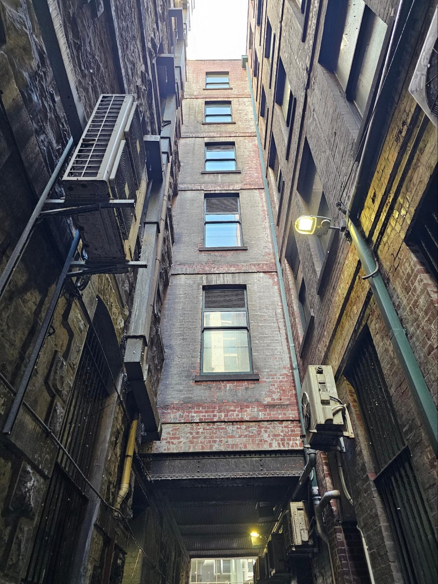
I-Beams vs. Steel AnglesThe shape and configuration of steel support materials play a direct role in determining its load-bearing capacity and rigidity. A flat bar of steel, while strong in tension and compression along its length, lacks the necessary stiffness to resist lateral forces or bending moments when loaded from above, in a flat position. By comparison though, shapes like I-beams and steel angles can be exponentially stronger, providing rigidity and load-bearing capacity through their geometric configurations. A flat bar of steel, when loaded with weight or mass from above, can easily deflect or buckle due to the lack of sufficient moment of inertia. Moment of inertia is a measure of a structural member’s resistance to bending or twisting, and it is directly related to the shape and distribution of material within the cross-section. A flat bar, with its material concentrated along a single axis, has a relatively low moment of inertia, resulting in poor rigidity and susceptibility to lateral deformation under load. However, when straight pieces of steel are interconnected at angles, forming shapes like I-beams or double steel angles, they gain significant rigidity and resistance to bending and lateral deformation. This is achieved through the strategic positioning of the material away from the neutral axis, increasing the moment of inertia and consequently enhancing the overall stiffness of the member.
In the case of an I-beam, the flanges at the top and bottom, connected by a web, create a highly efficient cross-sectional shape that maximizes the moment of inertia. The flanges resist the compressive and tensile forces, while the web resists shear forces, resulting in a lightweight yet significantly strong and rigid member capable of spanning long distances and supporting substantial loads. Similarly, double steel angles, formed by positioning, without even a physical connection such as welding or bolting two angle sections back-to-back, create a sturdy and rigid structural member. The alternating directions of the angles provide resistance to bending in multiple directions, while the interconnected configuration increases the overall moment of inertia and stiffness. Both I-beams and double steel angles can be used as girders or headers in masonry openings, such as door or window lintels. In these applications, they span across the opening and transfer the loads from the masonry above to the supporting elements on either side. The calculation of the bearing load resistance in a header configuration involves analyzing the combined effects of bending, shear, and axial forces acting on the member. The principles of structural mechanics are applied to determine the maximum allowable loads based on factors such as the material properties, cross-sectional dimensions, span length, and support conditions. Key calculations include determining the maximum bending moment and shear force acting on the member, calculating the section modulus and shear area to ensure adequate resistance to bending and shear stresses, and verifying the axial load capacity based on the compressive or tensile strength of the material. Additionally, deflection criteria may be considered to ensure the header does not experience excessive deformation under service loads, which could potentially compromise the integrity of the masonry above or cause functional issues with the opening.
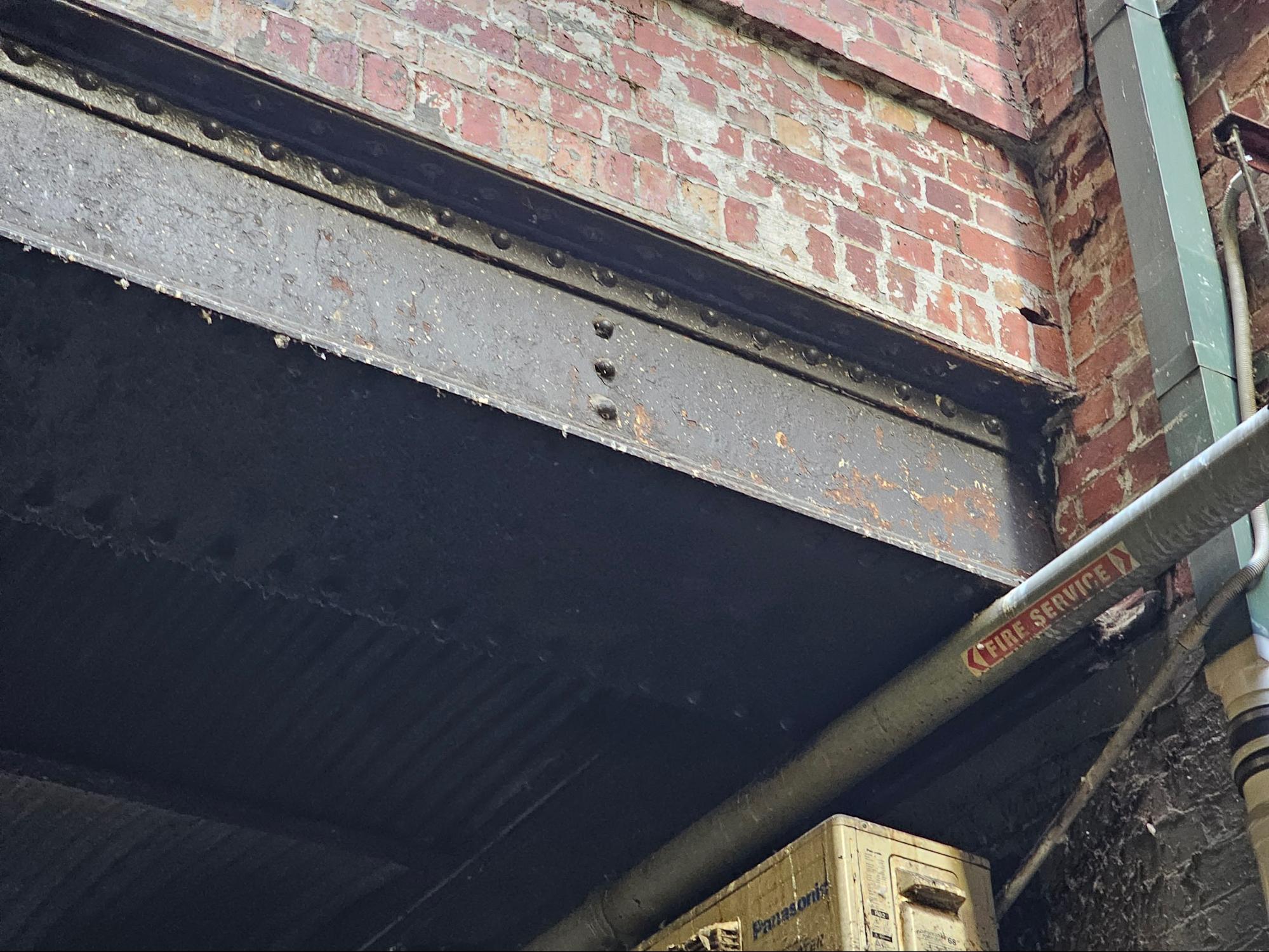
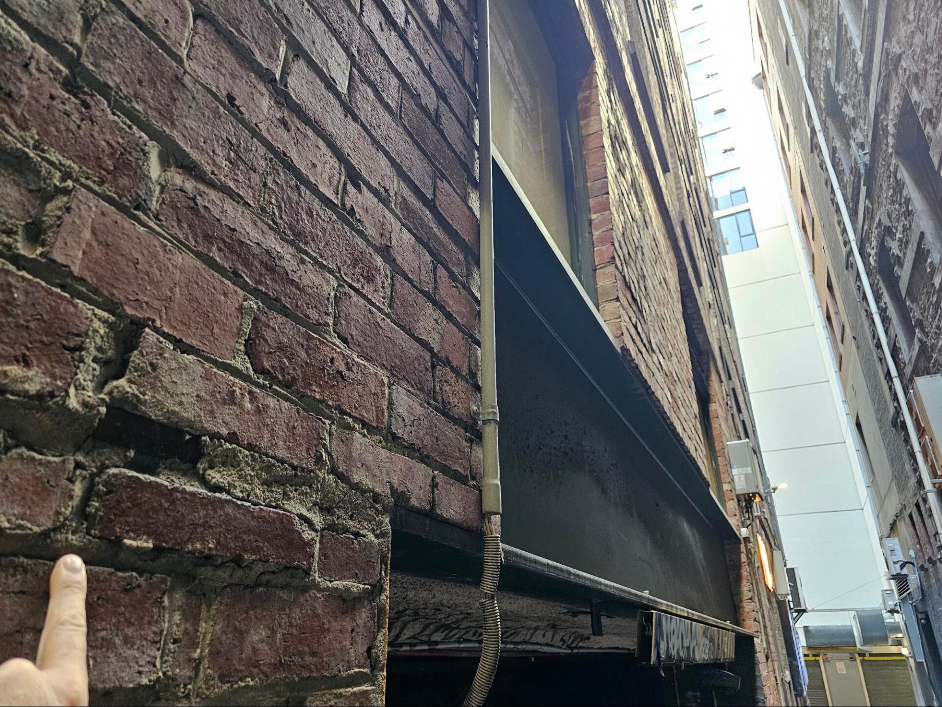
Brick Maintenance and Concerns at I-Beams and Steel AnglesWhen combining brick masonry and steel structural members, such as I-beams or steel angles, there are specific maintenance concerns and challenges that arise due to the inherent material incompatibilities. Although these materials can be integrated into a single construction system / assembly, they do not naturally bond well to one another, leading to potential separation and durability issues. One of the primary concerns is the lack of a strong adhesive bond between brick (mortar) and steel. Bricks are typically set using mortar, which forms a strong bond with the porous surface of the masonry units. However, the smooth surface of steel does not allow for effective mechanical or chemical bonding with the mortar, resulting in a weak interface and potential separation over time. At steel angle locations, bricks are generally set on top of the bottom leg of the angle, leaving the upper leg embedded within the brickwork. While this configuration conceals a portion of the steel angle, it also creates a potential path for moisture infiltration between the brick and steel surfaces, leading to accelerated deterioration, due to the occurrence of separation and delamination.
In contrast, when using I-beams as lintels or support members, the bricks are often set directly on top of the top flange. However, at the sides, both the top and bottom flanges must be embedded within the brickwork to ensure proper load transfer and stability. This configuration presents additional challenges in maintaining a durable and moisture-resistant interface between the brick and steel surfaces. Regardless of the steel member used (angle or I-beam), where bricks are set around the flanges or legs, regular mortar alone is not sufficient to ensure a long-lasting and durable installation. Regular mortar, when not fully embedded into the bed joints, can delaminate easily, leading to separation and potential structural issues. To address this concern, elastomeric sealants are often applied at the interfaces between the brick and steel members. These sealants are designed to accommodate movement and maintain a flexible, waterproof barrier, preventing moisture penetration and subsequent deterioration of the steel components.
Proper sealing is crucial because steel members embedded within masonry are more susceptible to accelerated moisture exposure, which can lead to oxidation and eventual failure. Even with protective coatings, the presence of moisture can compromise the steel’s integrity over time, potentially compromising the structural performance of the entire assembly.
Maintenance and inspection programs are essential for historic masonry structures incorporating steel members. Regular monitoring for signs of separation, cracking, or moisture intrusion at the brick-steel interfaces should be conducted. Reapplication of sealants or repair of damaged areas may be necessary to ensure the long-term durability and integrity of the structure. Additionally, measures to control moisture levels within the masonry assembly, such as proper drainage and ventilation, can help mitigate the risk of accelerated steel deterioration.
We can HelpWe can help with a variety of historic masonry restoration needs and upkeep, from modest tuckpointing and or repointing to complicated and extensive historic masonry restoration. Infinity Design Solutions is a historic restoration specialist contractor specializing in both historic masonry restoration such as tuck pointing our repointing, and brick repair. If you have questions about the architectural details or facade of your historic building in Washington DC, reach out and say hello and if we can help we’ll be glad to assist you. You can email us or call us on the telephone at the following link: contact us here. <p>The post Heavy Steel and Iron Girders Carrying Brick Masonry – Part II of II first appeared on Infinity Design Solutions.</p> Via https://www.ids-dmv.com/masonry/heavy-steel-and-iron-girders-carrying-brick-masonry-part-ii-of-ii/
0 Comments
Leave a Reply. |

About UsInfinity Design Solutions LLC (IDS) is a full service general contracting company in the heart of the Dupont Circle neighborhood of Washington, DC. We focus on repair and renovation of buildings and facilities in both historic designated neighborhoods and the commercial-zoned central business district of the city. Follow Us
|