|
The Infinity Design Solutions articles, on our website ids-dmv.com normally focus on the techniques and methodology related to historic preservation and restoration, particularly historic brick and mortar tuckpointing and repointing for preservation. Today, we’re taking a look at an interesting historic building with a completely modernized rebuilt structural interior. This particular building provides a very interesting perspective because the interior is completely unfinished, basically a blank or “white†space, so we have an unique opportunity here to see the bare bones of the hard structure of the masonry and concrete superstructure of the building. With technology changing around us, seemingly faster than ever, it feels like construction and building techniques are one of the few things in our world that hasn’t changed drastically with modern technology. Workers still toil with the heavy burden of lifting much of the buildings mass into place, unit by unit. Tradesman are still need to have refined and hard-earned skills to perform their respective trade. When you look closely though, there are many changes in the technology related to materials and methods of installation that have changed and amount to somewhat drastic changes in the overall methods of building construction. (Still yet, a revolutionary seed change, when workers and journeyman skills are replaced by AI and robots still feels far off, for now.) The outline of today’s discussion follows: The principle elements of the superstructure and load pathThe majority of historic brick row homes and masonry buildings in the oldest parts of Washington DC such as Capitol Hill are built with an exterior structural shell. That portion of the building supports all of the dead load of the floor systems and furniture and even the live load of people on the inside of the building, when people or furniture are standing on the middle of a floor in a room. For example, that floor system bears into pockets in the historic brick side walls of the building and those historic brick side walls of the building then transfer that weight from the floor system down to the footings, underground below the brick in the basement or crawl space of the building, generally buried relatively deep underground. By comparison, in modern construction footings are generally set at least a few feet underground, below the frost line but that’s not always the case with historic construction. Builders, over 120 years ago at the time of the start of the massive amount of construction that took place in historic districts of DC, such as Capitol hill, builders were aware of the impact and importance of burying footings below the frost line, but sometimes footings were put a little bit more shallow than they would be built today.
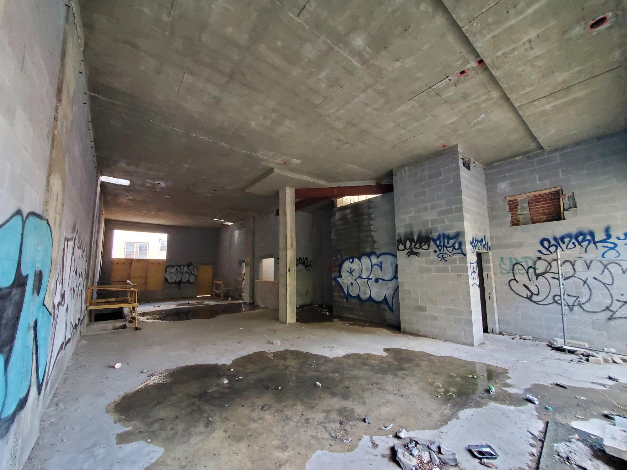
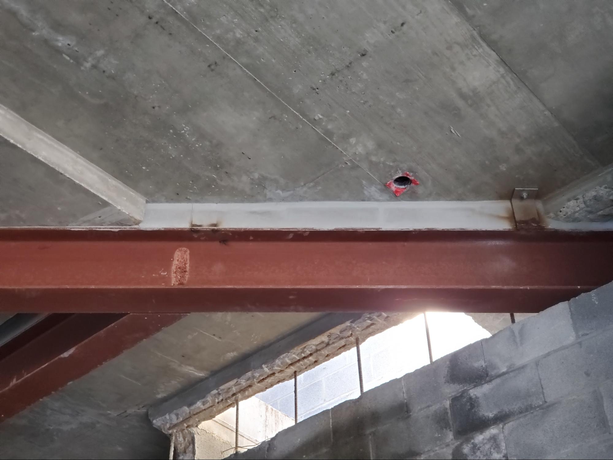
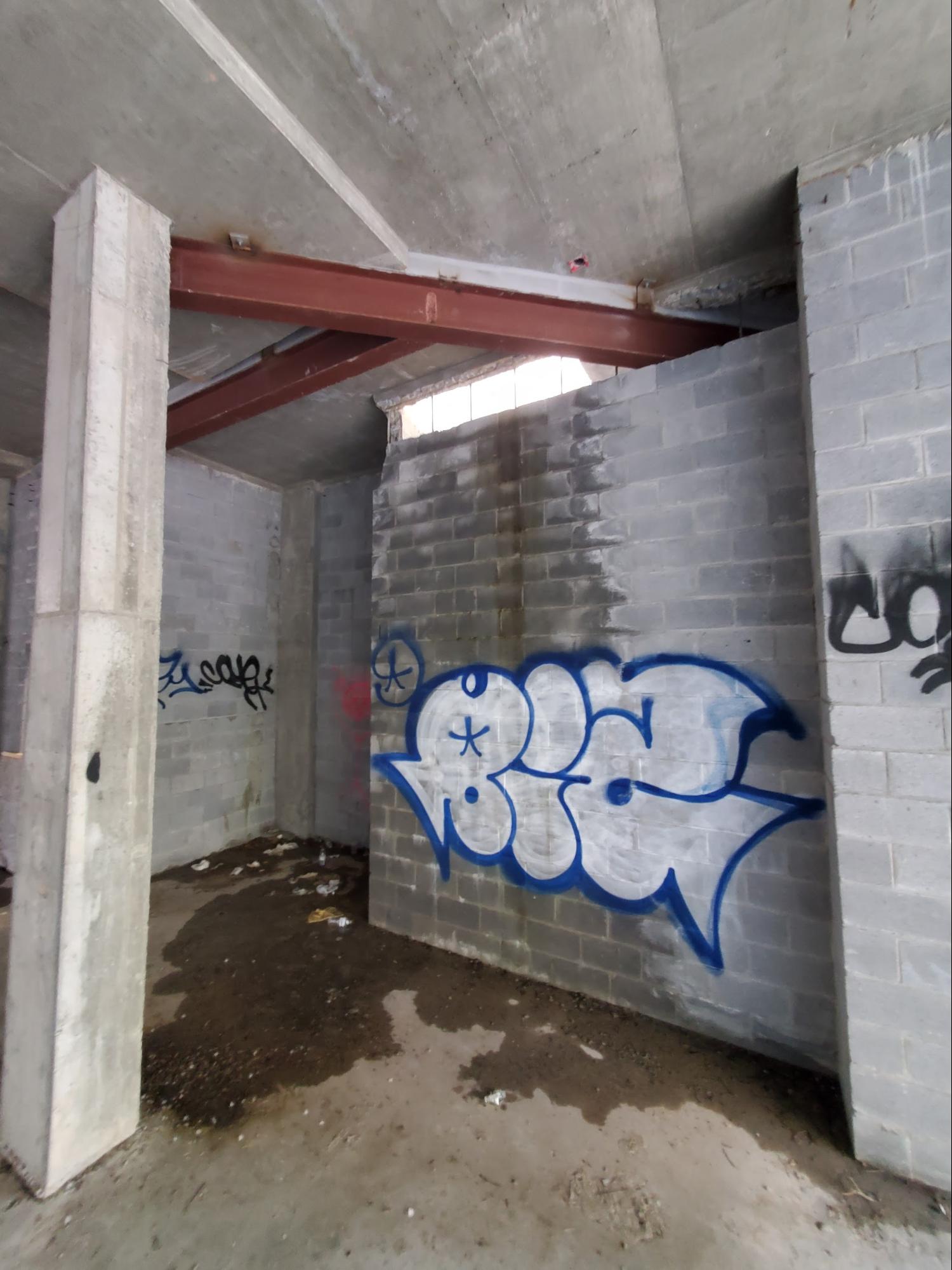
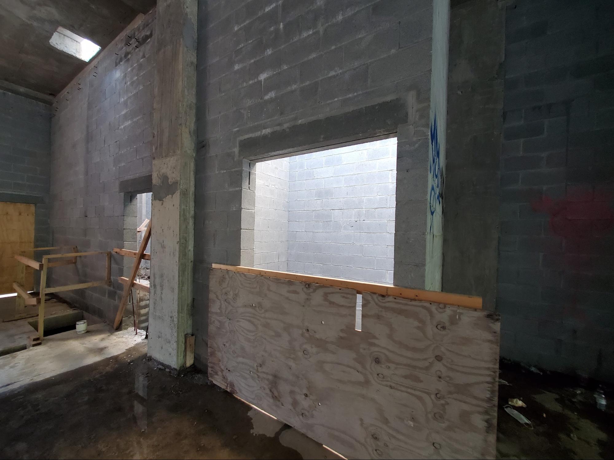
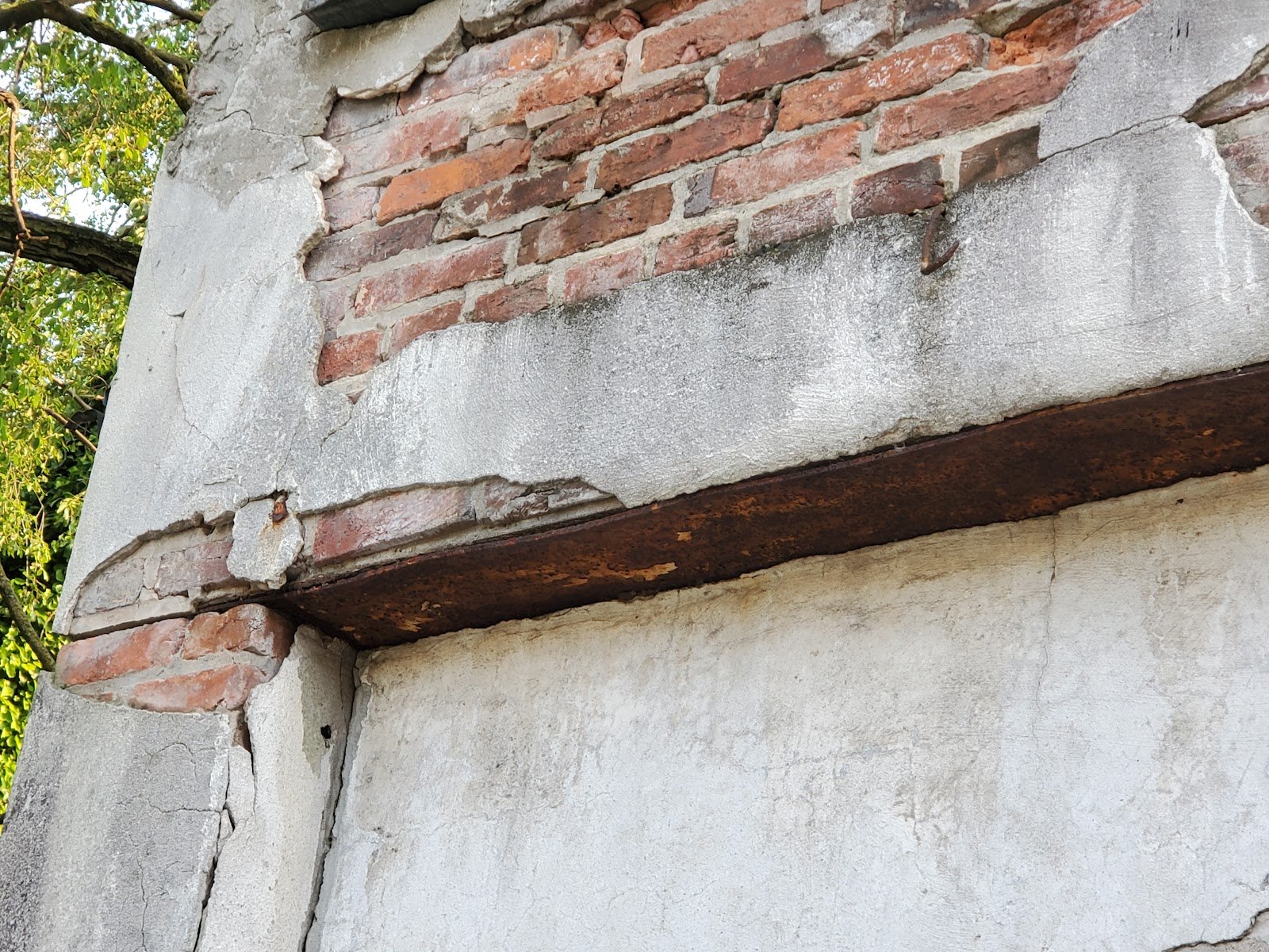
Transfer beams to open the floor spaceThis particular space though is different than the typical Capitol Hill row home or regular row building. There are several areas of buildings in Washington DC where commercial strips appear a little bit similar at the front facades of each respective building. They do appear historic, but there’s a big difference. Many commercial buildings are built extra wide to allow for the greater space needed in a commercial operation whereas a typical row home has regular floor plans with living rooms, bathrooms, bedrooms and hallways. In in some cases, these commercial buildings have been joined together and even expanded, in some cases doubled or even tripled to make extra large gathering spaces or entertainment spaces for establishments such as restaurants. Often, in historic buildings, converted to restaurants, you may notice columns at the interior of the open space. This building is built in a similar type of way, but the entirety of the interior of the building framing has been removed and replaced with modern construction, with the exception of the front facade. This gut and rebuild allows the interior to be built with entirely modern materials and methodology. Instead of using wood trusses for the girders and floor system, steel beams and concrete decks span the space horizontally. The next picture below shows a transfer beam which supports a portion of the concrete deck. Concrete decks are generally built with internal deformed steel reinforcement bars. In some cases larger span openings will be built with a two-way or four-way post tension or pretension system where highly tensioned strong cables are used in compressive force in lateral direction with the slab to give the slab resistance from tensile deflection. Here though, by comparison to larger commercial concrete buildings, this system is relatively simple and post tension or pretension cables are not used in the interior space of the slab. Deformed rebar is used, but not tensioned, just internal to the concrete deck to provide tensile resistance. Compressive strength is inherent in concrete, meaning that concrete can essentially resist being smushed between heavy forces, inherently or natively, as a elemental nature of the concrete itself. However, concrete and masonry for that matter as well do not have inherent significant tensile strength or force resistance. When positioned or used in a configuration which requires tensile resistance masonry and concrete generally require implementations or alternative methods of combination with other materials to provide additional tensile force resistance strength. The steel beam in the photo below spans from a column to the top of a block wall. The block wall is vertically reinforced with concrete in every other cinder block vertical cell run. For this reason the block wall has relatively strong compressive strength and the spanning steel beam can support the column header although it doesn’t need much support, but it can also support a portion of the concrete deck above. In this case the space between the steel beam and the concrete deck has been filled with a non-shrink nonmetallic grout. In the picture below the grout looks very similar to regular high strength concrete but it is actually a different material without the typical variety of larger aggregate normally found in concrete. The non-shrink grout is applied after the beam is installed to fill the void between the concrete deck above and the steel beam. This grout then transfers the load of the deck to the steel beam.
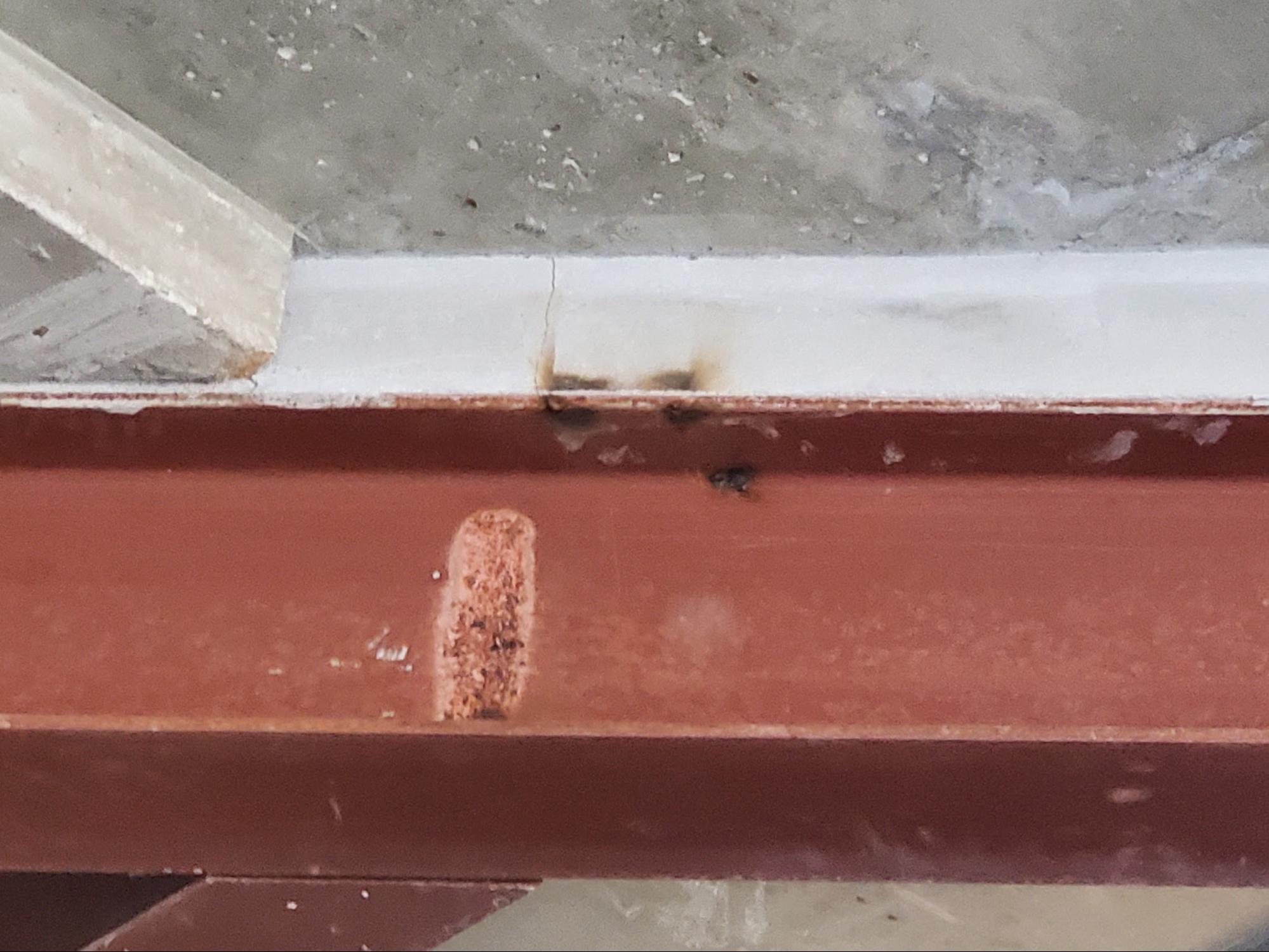
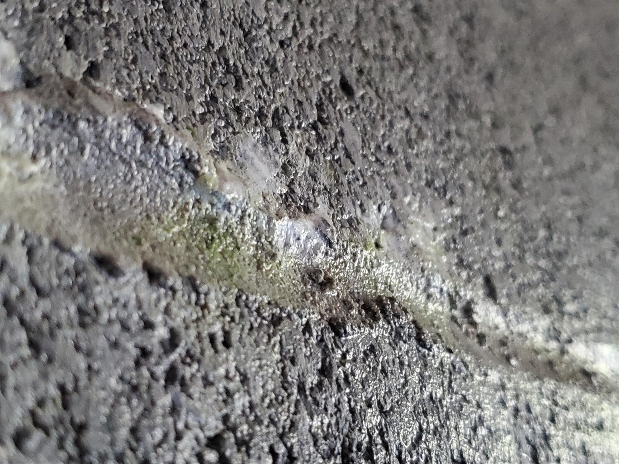
A closer view of that non-shrink route atop the shop primed steel beam follows below.
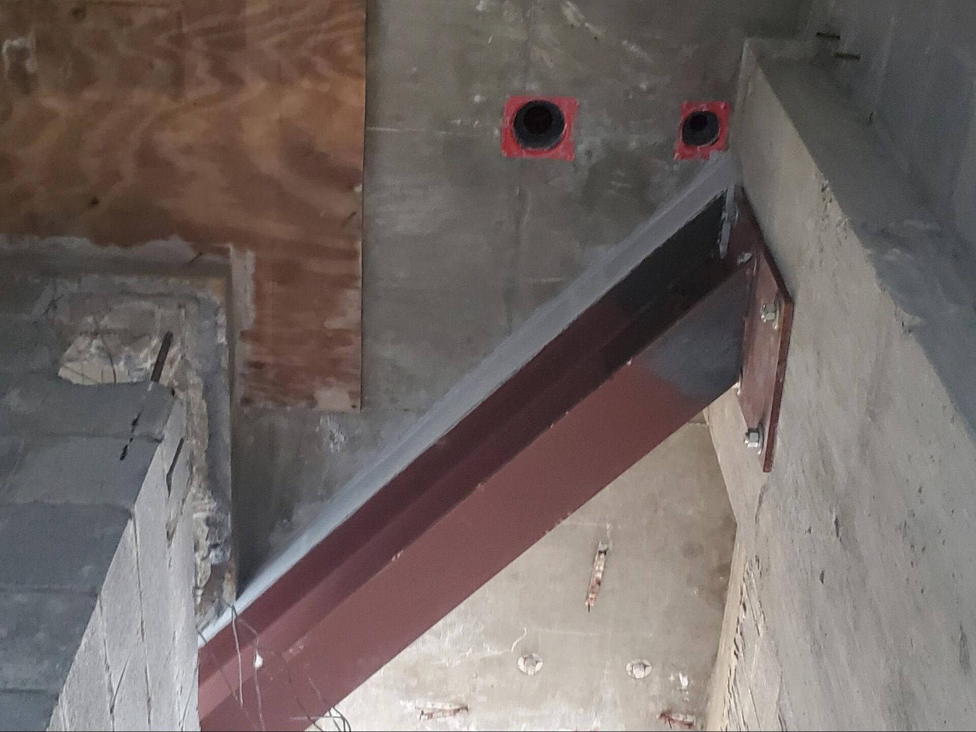
Another similar transfer beam is installed between the block wall and the elevator shaft. At the edge of the cinder block shaft wall, you can see a remaining portion of plywood form board. Plywood form boards are used to create a temporary deck upon which the steel reinforcement and wet concrete are laid before they harden in the casting and curing process. Once the concrete is hard, essentially cured for a period of at least 7 days, varying and depending on the type of concrete specified and used, the plywood will be stripped and removed. In this particular case though the remaining board shows an example of what the entire deck would look like at the time of pouring the wet concrete. Those plywood form boards are generally supported by a large aluminum and wood beams set on structural scaffolding, used in the temporary forming and shoring assembly, those aluminum beams are most commonly, A21 beams. The “21†in the name denotes the 21 foot length.
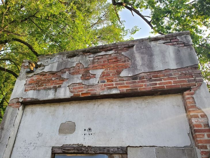
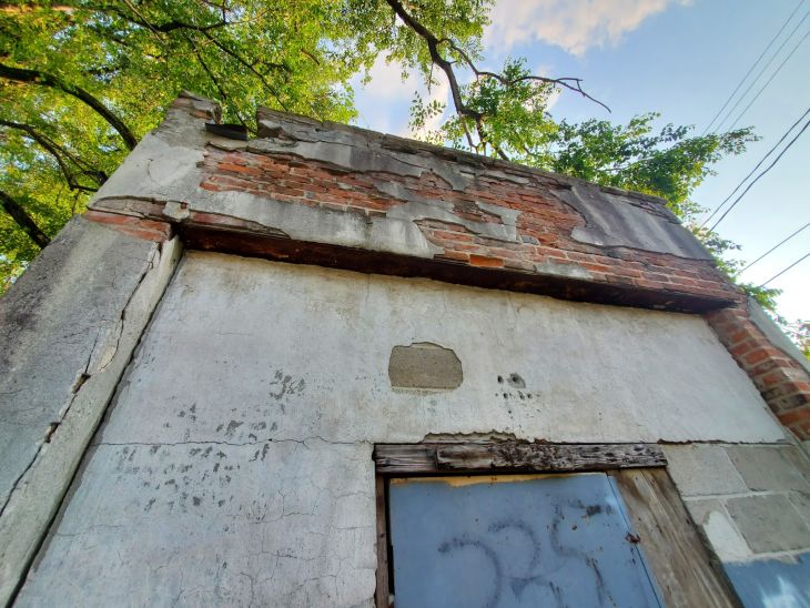
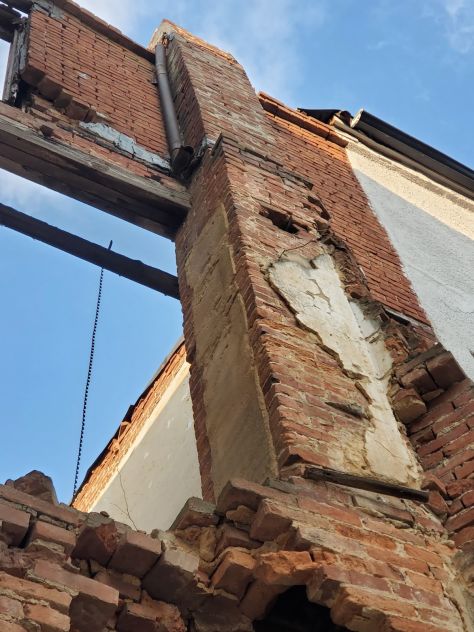
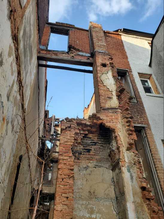
Insidious damage from openings in the building shellIn this particular case, construction has stopped during the pandemic between phases of construction. The job site has been abandoned and the areas of the roof are unfinished and the stair and elevator shafts are wide open without a roof or membrane to protect the building from the exterior elements of weather and precipitation. Water has been seeping into the building for some time and has caused damage and deterioration, similar to the deterioration we find at historic brick masonry facades, but slightly different. The block in this building is built with a type-S mortar. Historic brick masonry, for example, is generally originally built with a low compressive strength high permeability lime mortar. Although historic brick and associated mortar generally has lower compressive strength and higher permeability it can remain relatively undamaged from the majority of typical weather patterns if pointed or repointed or tuck pointed on a proactive schedule.
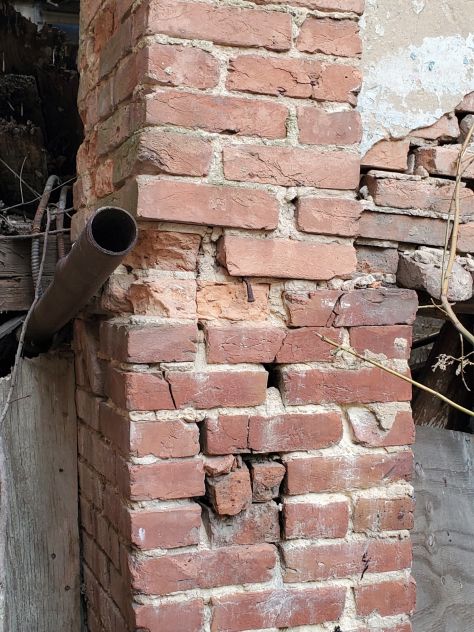
Similarities to historic masonryExposure to weather and precipitation will inevitably lead to the deterioration of historic brick mortar, if historic facades are not properly maintained or protected. Mortar, especially historic brick mortar is porous, (by comparison, modern mortar such as high strength Portland motor has much lower permeability yet still is not completely impermeable or undamaged by the deleterious effects of exposure to precipitation) it can absorb water, and even wick water inwards through capillary action at open voids and even through microscopic voids and capillaries. When mortar is exposed to rain or high humidity levels, water can penetrate the surface and infiltrate the mortar joints. This can weaken the mortar and lead to its deterioration over time. In climates like Washington DC, the presence of moisture in mortar can be particularly damaging. When water within the mortar freezes, it expands, causing internal pressure. This expansion can result in cracking, spalling (surface flaking and delamination), or disintegration of the exterior surface of the mortar. With repeated freeze-thaw cycles, the damage can worsen at a nonlinear, accelerating rate. Efflorescence is a white crystalline deposit, similar to the salt we are most familiar with, which appears on the surface of mortar and masonry through successive cycles.of hydration and dehydration. The process occurs when salts present in the mortar dissolve and The next picture below shows a different motor joint with clear signs of Biocolonization or plants or moss growth on the surface of the block at the mortar joints.
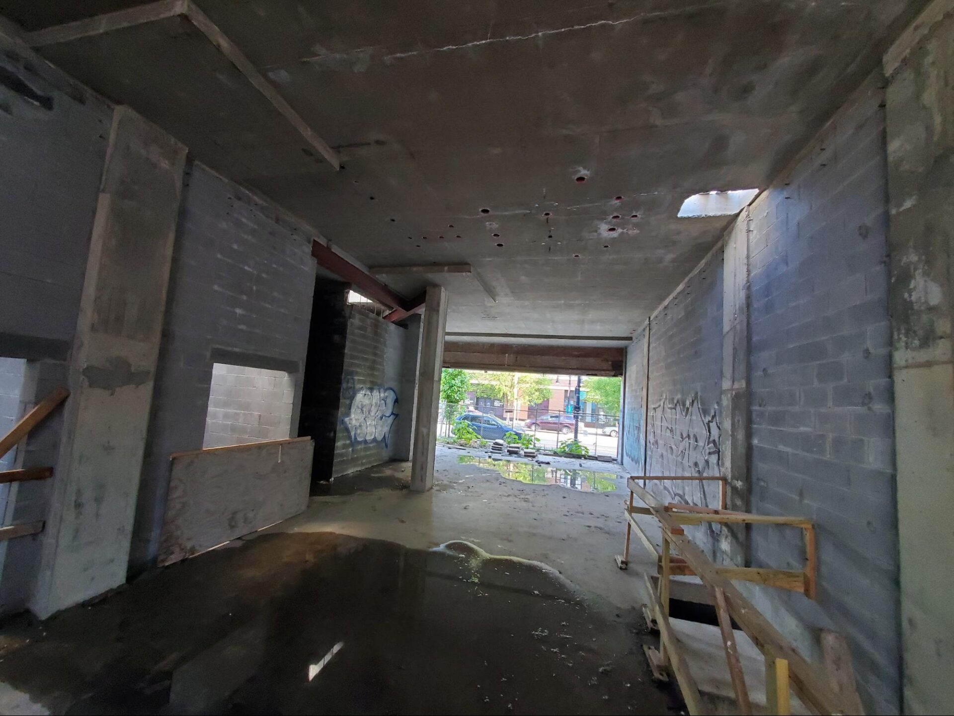
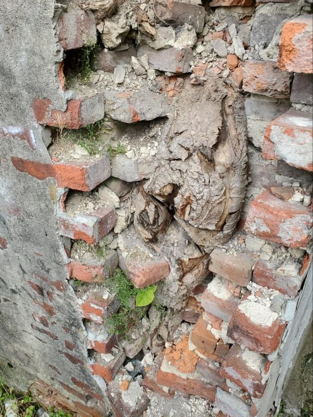
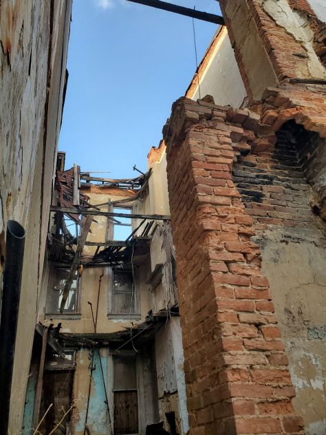
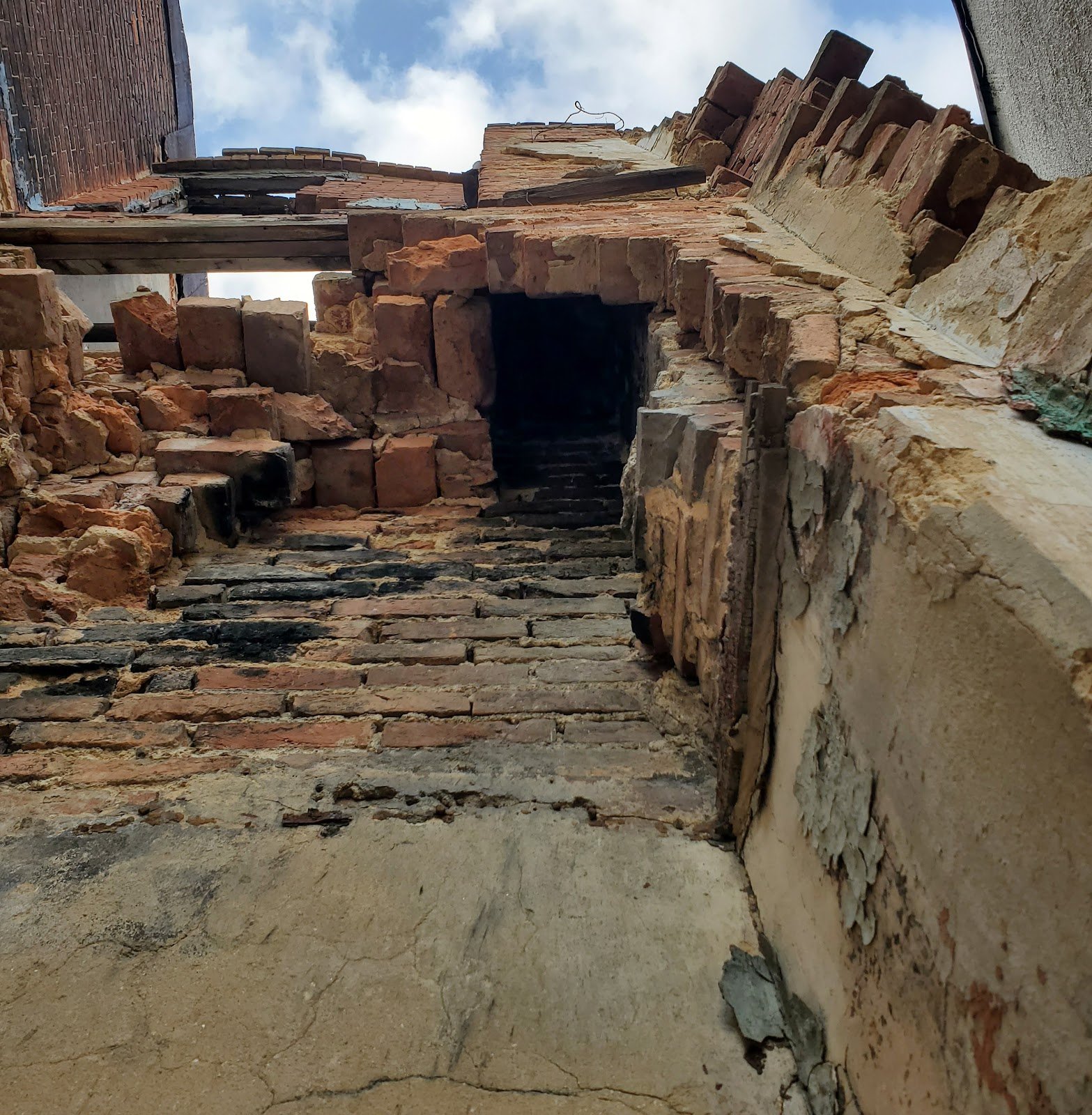
Periodic repointing or tuckpointing involves removing damaged or deteriorated mortar and replacing it with fresh mortar, can help restore the integrity of the masonry structure. Care should be taken to use appropriate restoration methodologies and appropriate historically compatible materials that do not further harm the mortar and or lead to accelerated deterioration of the masonry construction or facade. As always, it is important to note that when managing the preservation of historic structures, guidelines and principles should be followed to ensure the appropriate methods and materials are used for maintenance and repair. Consulting with historic preservation experts such as Infinity Design Solutions is recommended to ensure the proper care and preservation of historic mortar. The picture below shows an area of the open floor of the building. Rainwater has entered the building, unmitigated for an extensive amount of time and cause damage, not just to the walls, but also to the concrete floor system. This damage can be repaired and halted in place. Once the building is dried and repaired, conditions can be ameliorated.
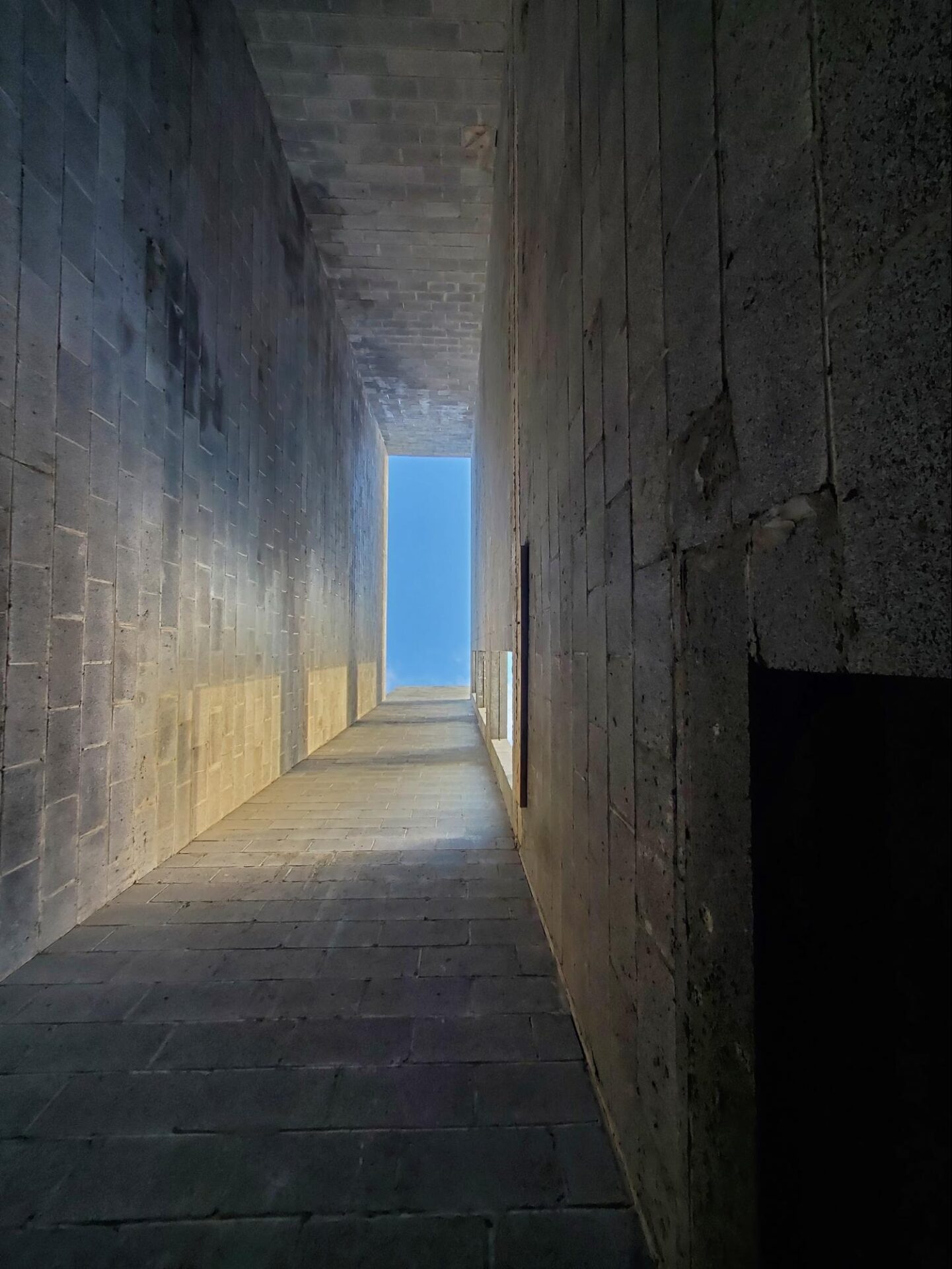
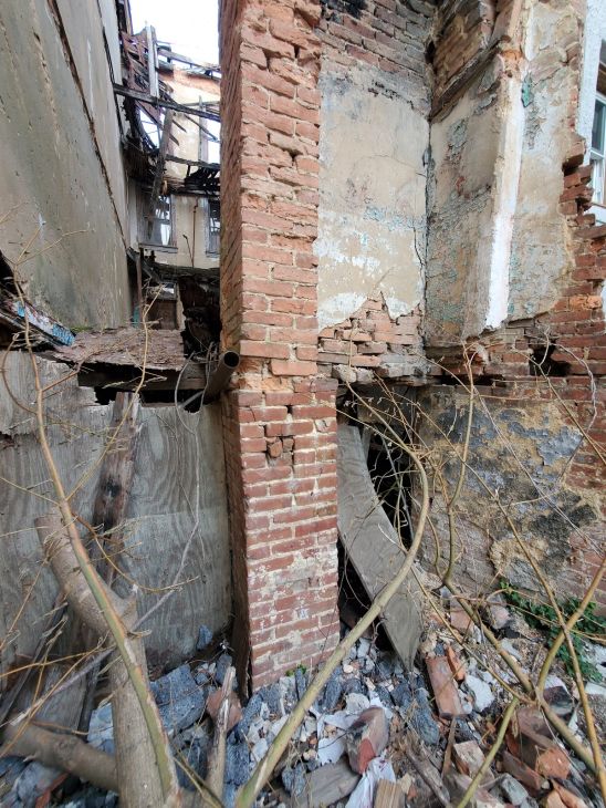
One of the several places where the roofing system is completely omitted is shown below at the future elevator shaft.
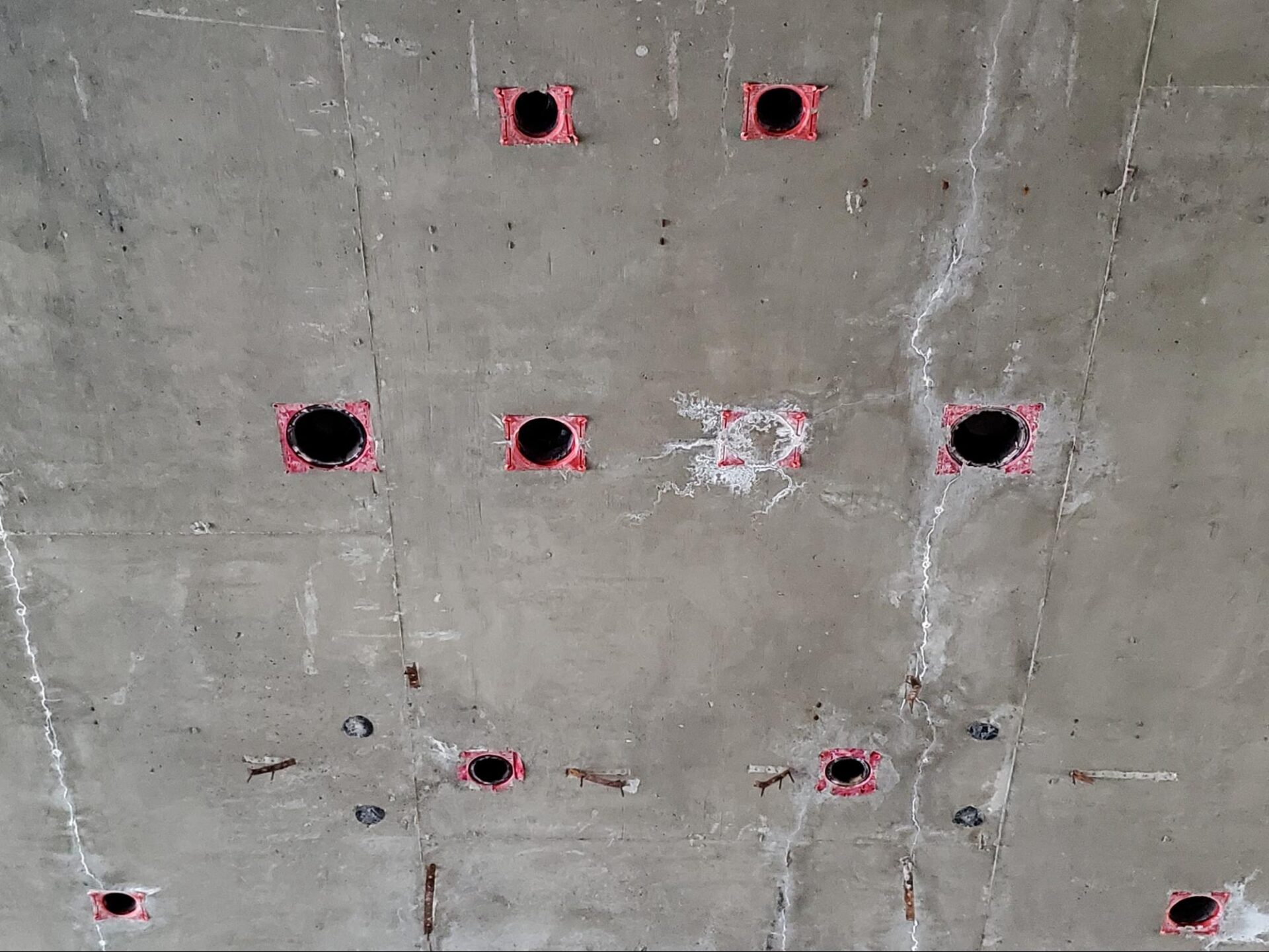
Working with concrete floor deck systems is significantly different than traditional historic wood framed systems that use a tight joist layout covered with a wood floor sheathing. In historic and contemporary wood frame systems, holes can be drilled or bored through floor systems to allow the passage of plumbing pipes, drains, and vents. Here though, for example in a concrete deck system the layout of plumbing piping must be measured and planned ahead of time so that blackouts or poor stops can be cast into the concrete to allow later passage of pipe runs. As an alternative to proper planning, core drilling of concrete is also an option, but generally significantly more costly than proper planning.
Opening spans and header requirementsBefore the advent of mass production steel mills and ensuing relatively low cost steel and precasting cement plants (generally requiring the re-invention and use of Portland cement) availability for building construction, alternative historic methods of opening headers involved pure masonry and hybrid masonry-wood headers. Roman headers which are self supporting but require headspace are common in large floor to ceiling height buildings. Often though shorter segmented brick headers were used in Washington DC and Capitol Hill.
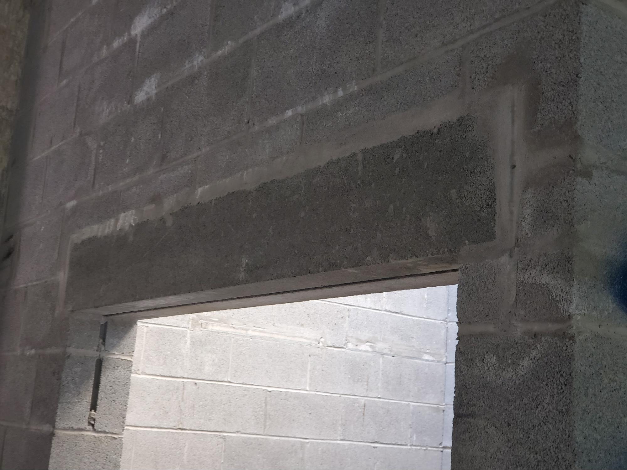
The picture below shows a closer view of a masonry lintel. The masonry lintel is cast and cured in an off-site factory. It’s not visible from the surface, but embedded in the masonry header, deformed steel reinforcement bars are inserted to provide tensile force resistance.
Historic masonry upkeep and preservationTo properly maintain, repair, and care for these historic buildings, a knowledge, interest and understanding of historic building principles is required. Here in Washington DC, historic masonry buildings are extremely expensive and the amount of financial loss caused by improper repointing and low quality construction is staggering. However, in addition to the direct financial value of the property, there is also a cultural loss when historic buildings are damaged. By comparison, consider neighboring poor cities, when historic buildings are damaged, it’s not just the loss of value to the property owner, there’s also a loss to all inhabitants and visitors of a city, present and future, who care about architecture, history, and culture. We encourage all of our clients, and all readers of this article and to our blog in general, to prioritize the historic built environment of Washington DC and neighborhoods such as Capitol Hill, Dupont Circle, and Georgetown and become educated on on the difference between proper historic preservation versus improper work which leads to significant damage to the historic fabric of a building. From a conservation and preservation perspective, several approaches can be taken to improve conditions related to deteriorated historic brick masonry. Primarily, lime mortar brick joints and low temperature fired soft red clay bricks should be inspected and checked on a routine maintenance schedule, either seasonally or at least annually. If brick masonry is kept in good condition, the life of embedded wood elements can be significantly extended. Hire a professional contractor which specializes, understands and appreciates historic construction elements and buildings. You can learn a lot more on our blog. Feel free to check it out. If you have questions about the historic masonry of your building in Washington DC, contact us or fill out the webform below and drop us a line. We will be in touch if we can help. <p>The post Structural Load Path In A Converted Historic DC Commercial Masonry and Concrete Building first appeared on Infinity Design Solutions.</p> Via https://www.ids-dmv.com/masonry/structural-load-path-in-a-converted-historic-dc-commercial-masonry-and-concrete-building/
0 Comments
What Is Functional Engineering And How Do You Protect Masonry Facade?This week, we present the third part of a three part series, a continuation on the discussion about the Vitruvian Wave and projecting elements of masonry facades. The outline of the articles in this series follows below:
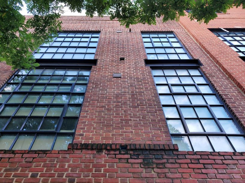
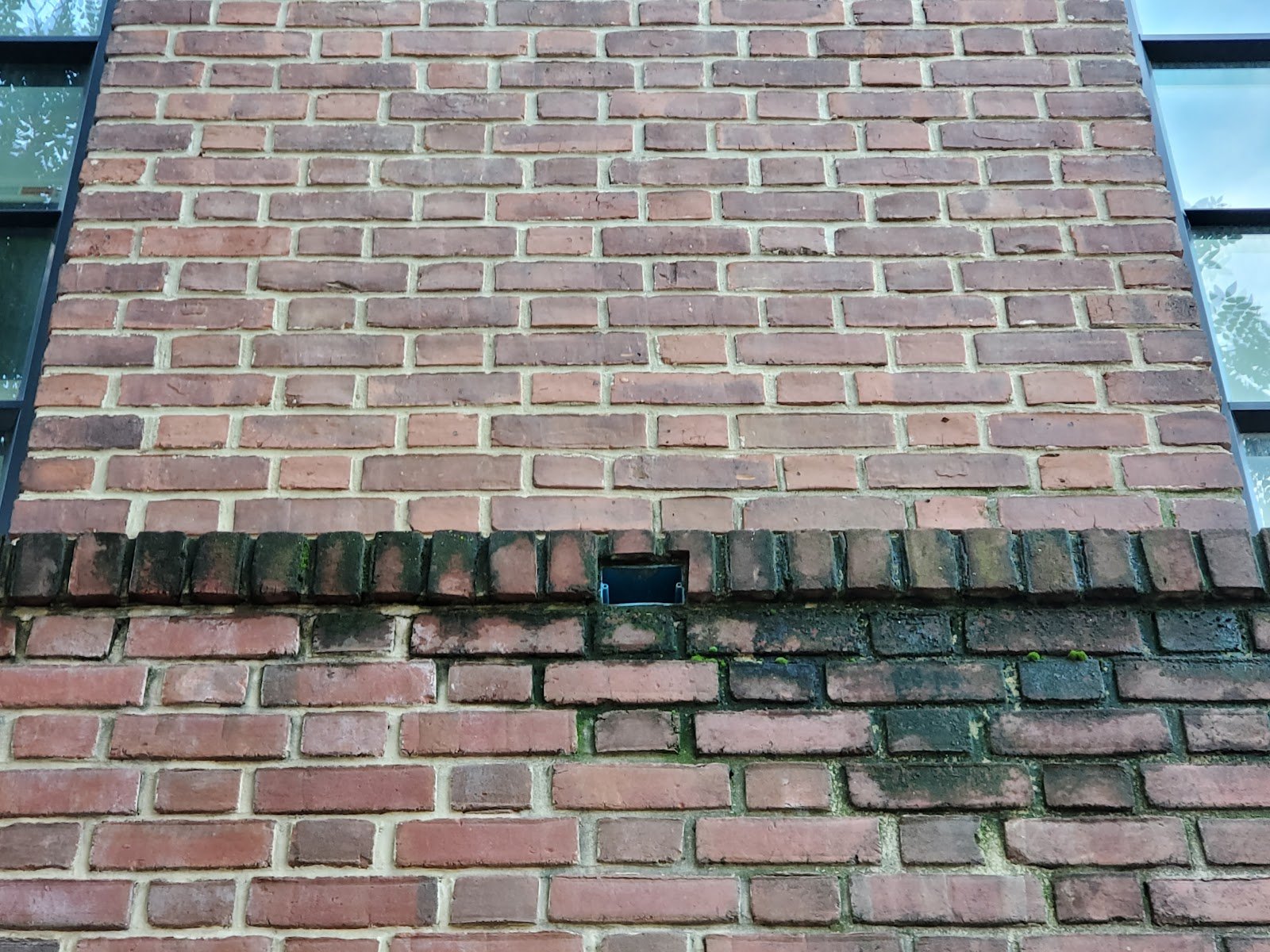
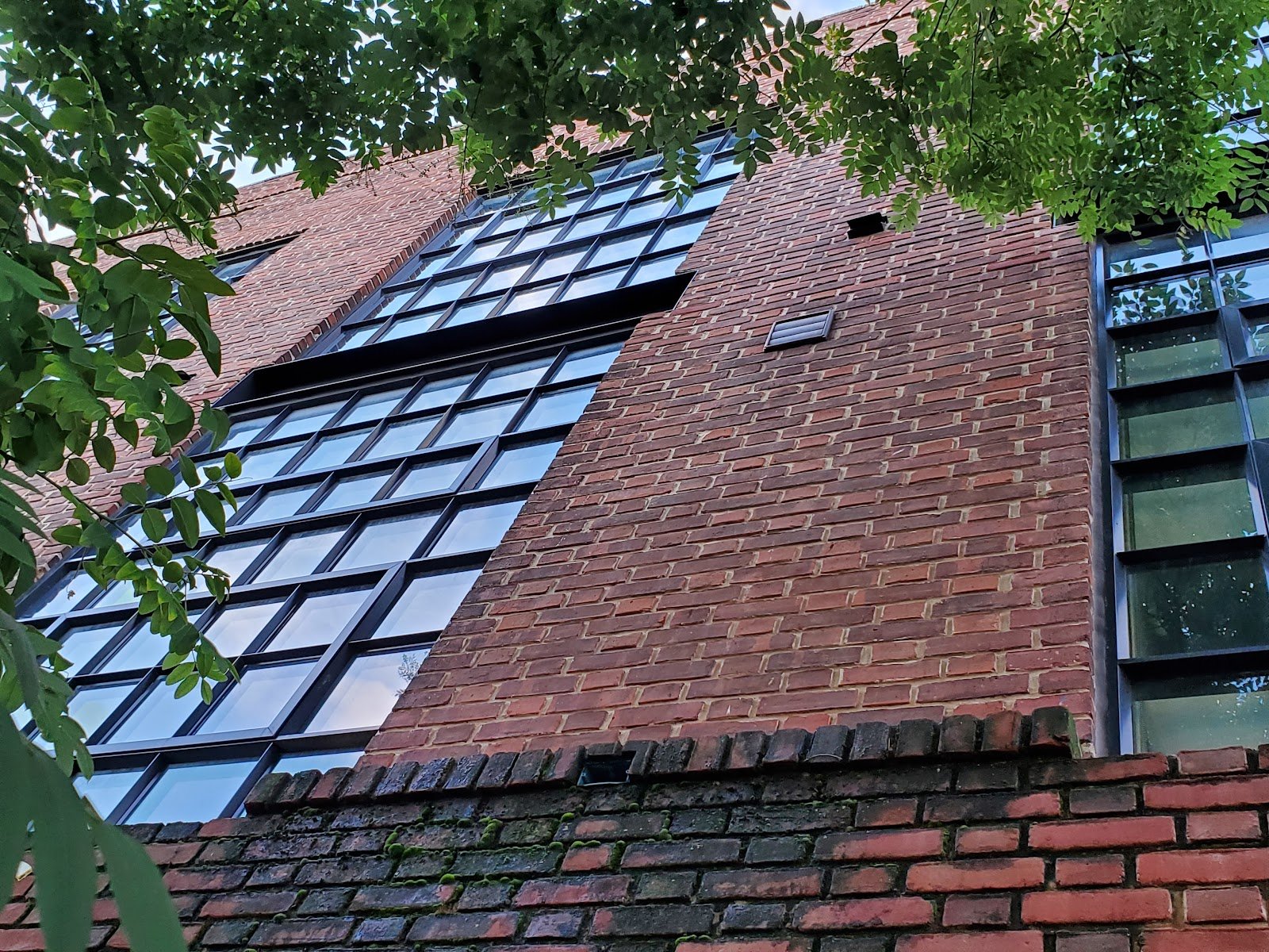
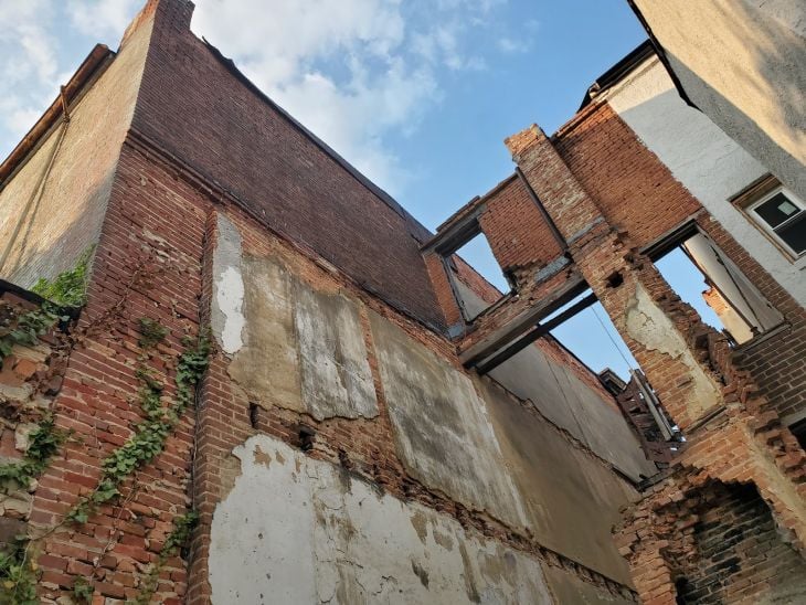
In last week’s article we took a look at an existing historic building with a light gray sandstone facade. The masonry frieze at the top of the ground level in the iron spot brick facade showed signs of excessive water entry, deterioration, and discoloration. A link to that blog follows for reference: Vitruvian Waves and Architectural Friezes – PART II Today we’re looking at a very similar problem or defect causing deterioration through water entry and accelerated decomposition of brick masonry at a building facade. The particular context related to the frieze that we saw in the last article, was that that frieze created a ledge or projection slightly away from the facade of the building. Protection, projections, and cappingThat projecting ledge essentially protects the lower portion of the facade below the frieze area, essentially creating a miniature awning or roof above the lower portion of the facade. During heavy precipitation with high winds, this type of projection would be largely ineffective to protect the lower area of the wall, however, during the majority of precipitation events with low wind, this type of facade projection is very effective to keep the lower area of the wall relatively dry. Masonry and brick facades of historic construction are generally very resistant to moderate exposure to the elements including precipitation for up to hundreds of years, but repeated exposure to moisture will break down the elements of brick and especially lime mortar. Further below we discuss the importance of tuckpointing, repointing, routine maintenance, and upkeep. We also looked at the example of a kerf or chamfer at the outer edge of tge underside of a projecting facade element, working similarly to a typical metal drip edge in contemporary or modern construction which allows water to roll off of an edge of a projection without rolling back to the vertical facade. Unlike non-water based liquids, water has a cohesive bond innate to the molecular structure, so water has a tendency to roll back and even stick to things a little bit and without a drip edge or chamfer cut into the underside of the projecting masonry, as was shown in our example, water can run from a standing or projecting ledge, back to a facade. In this case though this type of detail allows the water to drip away from the building without running all the way back, in the absence of significant winds. Similar to that iron spot brick masonry building in the previous blog, the building in the picture below was built with a structural brick facade. The lower portion of the building projects farther away than the upper portion of the building. The upper portion of the building was added as part of a retrofit after the original construction. The lower portion of the building below the projecting area of the wall was original. The designer did a good job to match some of the historic masonry details from the original construction. For example, they have used a structural red brick in a Flemish bond for the construction of the upper portions of the wall, to continue the pattern of the original wall.
BioconalizationThe older or more original lower portion of the wall was tuckpointed or repointed with a similar color mortar, as used in the newer portion of the wall above. In both the picture above and the picture below, you can see a dark area below the projecting ledge of brick. The mortar joints of that area and even the face of the brick units themselves are stained dark with dirt and bioconalization. Bioconalization is the phenomenon of moisture Infiltrating into masonry services sufficiently to break down the exterior surface of the mortar into base components such as sand and silica, allowing plant growth. As the mortar breaks down, plants can begin to take root on the face of that masonry, especially in conditions with repeat and continuous high moisture. The surface of the masonry essentially becomes a perfect breeding ground for certain types of moss and plants. After moss begins to grow on the surface of a brick masonry facade, as shown in these photos, the plants that grow on the face of the masonry will evolve in succession, each breaking down the masonry and brick mortar farther so that higher forms of plant growth can take root deeper into the brick surface.
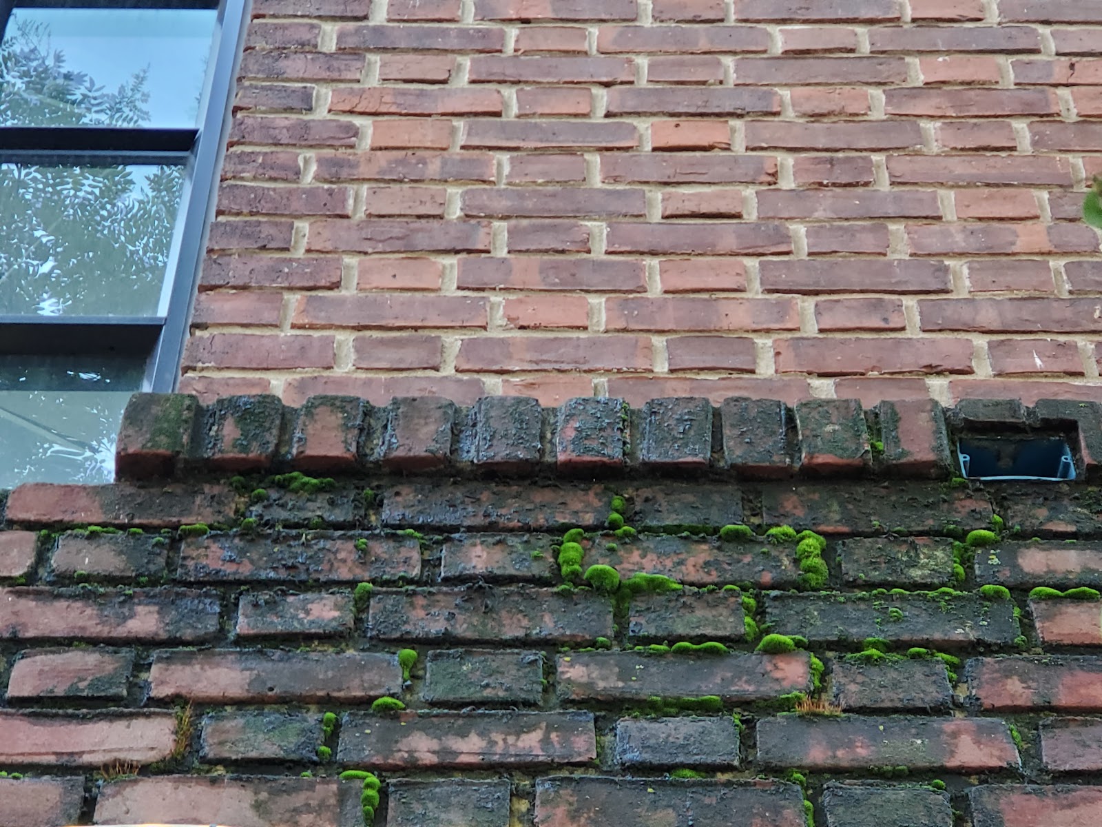
Mortar DeteriorationThis sort of deterioration happens at an accelerating rate, as one area of masonry begins to deteriorate, that deterioration continues but at an increasing rate, faster and faster. Usually, in a mathematical presentation, this sort of increasing or accelerating deterioration would be described as non-linear, as the curve of deterioration continues but at a greater degree at each step in progression. From a building life-cycle management perspective, it is extremely beneficial and financially rewarding to invest in upkeep and preventative maintenance in historic brick facade buildings. The brick ledge shown in these photos is a rowlock course of masonry at a relatively low-slope. Sills, as used in windows or other projecting horizontal surfaces should be built with a cant, bevel, or slope from the exterior facade area of construction towards the outermost edge of the facade. An intended slope at a projecting horizontal area allows water to passively drain away from the building. This slope is a subtle yet important detail of design, at the majority of sills and horizontal areas. These areas bear the majority of residual repeat exposure to precipitation and hydration.
A rowlock course of masonry, as used in this particular example, is technically an acceptable method of creating a sill, but generally for masonry copings or cappings at horizontal areas such as ledges, sills, retaining walls, and other exposed horizontal surfaces, it is sometimes (depending on configuration) a better practice to use longer units of masonry or stones that are set in a stretcher position. The difference may appear subtle in the overall design of the facade or layout of the construction, but effectively the ratio of joints to the respective masonry surface is decreased significantly by flipping the layout to a stretcher configuration. Sometimes though a rowlock course is structurally necessary because the brick spans both courses in a double whythe construction, structurally tying the top of the wall together between individual wythes of brick. That happens to not be the case though in this particular example, both because of the upper portion of the wall only being recessed 4″ shy of the lower facade and since it is a Flemish bond the wall is already built with high interconnection between wythes of brick. There are six main facings for brick positioning. A brick has 6 sides, but each of those sides have a matching opposite face. In total, each brick has 3 different side types that can be used as a facing, but each of those sides can be set in a vertical or horizontal running position. These six main facings follow: shiner, soldier, sailor, stretcher, rowlock, header. We have an encyclopedia of historic masonry restoration terminology on our website where we have listed more detailed descriptions of each of these facing types there on outer site, at the following link: Facings, of ashlar and brick masonry
Brick, or ashlar masonry facings, refer to different orientations and placements of bricks in a brick wall or facade. Here’s an explanation of each brick facing:
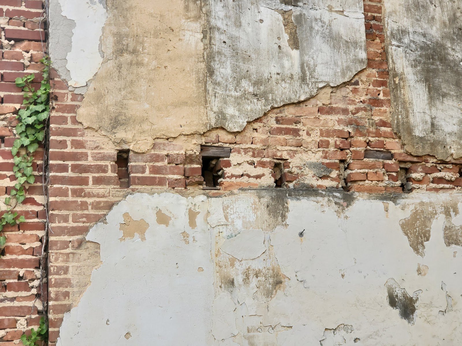
These brick facings allow builders and architects to create different visual effects, patterns, and structural characteristics in brick walls, adding variety and interest to architectural designs. If you look closely, in the photo below, you can see that each area of exposed masonry, at each recessed mortar joint in the brickwork below the projecting ledge has dark areas of dirt and bioconization from exposure to excess moisture that has permeated through the projecting sill. This damage has taken place over years, not just one season of exposure to the elements, yet the damage is insidious because it has caused the breakdown of the mortar joints around each area of brick.
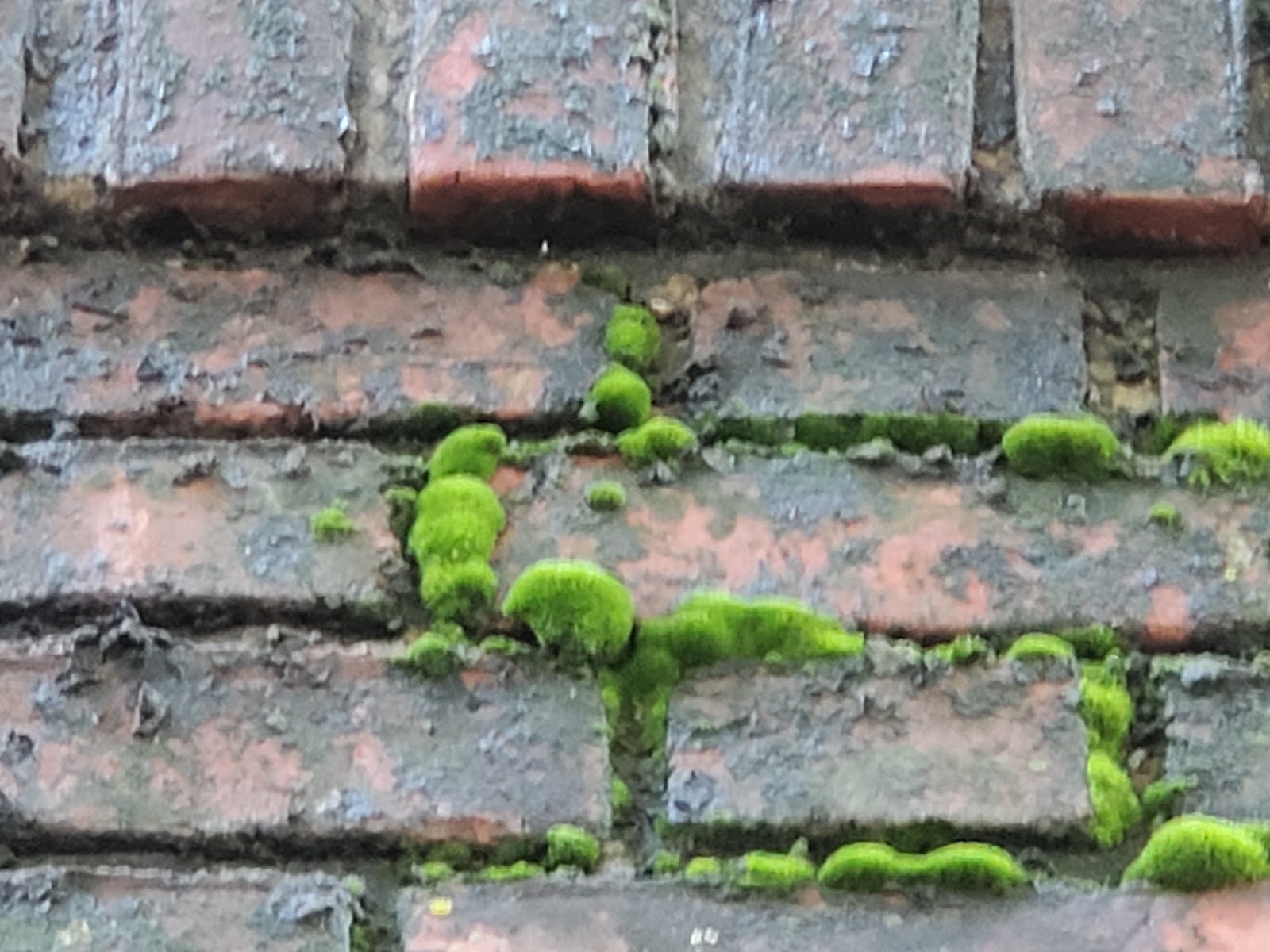
The next pictures below show a different but adjacent area of the same wall. The big causal factor for the increased amount of biocolonization between the section of the wall shown in the photo above versus the one below is that the one below is shaded by a tree. There is a tree growing in the city sidewalk, right in front of the area with significantly higher bioconalization. Essentially, this means that since this portion of the wall is shaded and has less exposure to sunlight, it dries out much slower, therein has longer periods of hydration at or following each precipitation event and therefore experiences slightly more water damage at each successive rainfall. This picture, and the resultant comparison with photos above show a drastic visual contrast. Masonry preservation is costly, but can save so much!
Tuckpointing and repointingTuckpointing and repointing are crucial processes for preserving the integrity of a masonry facade, enhancing building longevity, and reducing overall repair costs. We take a closer look at the process below and describe how it contributes to these benefits. Tuckpointing is a technique used to repair deteriorating mortar joints in a masonry wall. Over time, as shown the photos here at the projecting sill, the mortar between bricks can degrade due to exposure to precipitation and related moisture. Tuckpointing involves removing a portion of the outermost deteriorated mortar and replacing it with new (yet historically compatible) mortar, which restores the structural stability and moisture mitigation of the wall or facade. It’s extremely important that the mortar used in pointing is historically compatible. This, more than anything else, is the number one difference between good and bad pointing work. There are tons of differing characteristics related to quality and professionalism, but if you hire a cheap contractor to point your facade, and they don’t have knowledge, training and experience to get the mortar right, the damage caused by using the wrong mortar can be disastrously expensive. By properly restoring deteriorating mortar joints through tuckpointing, the integrity of the masonry facade is preserved. Restored and tuckpointed mortar joints prevent moisture infiltration, reducing the risk of water damage to the underlying substrate and internal building structure. Moisture intrusion can cause various problems such as efflorescence (salt deposits on the surface), mold growth, freeze-thaw damage, and biocolonization. The deleterious effects described can all ultimately compromise the stability of the masonry wall. Tuckpointing ensures that the facade remains strong and resistant to external elements. By preventing moisture infiltration and subsequent damage, tuckpointing extends the lifespan of the masonry facade and the entire building. It helps maintain the structural integrity of the walls, preventing cracks, displacement, or even eventual collapse. Timing matters, addressing mortar deterioration early on, tuckpointing minimizes the need for more extensive repairs or complete wall replacement as we have shown on our website in the moat extreme circumstances. Proper tuckpointing seems expensive, but it can last for decades and can lead to significant cost savings in the long run. By addressing deteriorating mortar joints at an early stage, you can prevent further damage to the masonry facade and the underlying structure. This proactive approach avoids the need for extensive repairs, reconstruction, or even replacement, which can be considerably more expensive. Regular tuckpointing maintenance is a cost-effective requirement to preserve the facade, enhance building longevity, and avoid costly repairs or renovations down the line. In summary, tuckpointing and repointing play vital roles in preserving a masonry facade and increasing building longevity while reducing overall repair costs. These maintenance practices address deteriorating mortar joints, prevent moisture infiltration, maintain structural integrity, and help avoid more extensive and expensive repairs. By investing in tuckpointing, building stewards and owners can ensure the longevity and durability of their masonry facades while minimizing the need for costly repairs or reconstruction in the future.
Historic masonry upkeep and preservationTo properly maintain, repair, and care for these historic buildings, a knowledge, interest and understanding of historic building principles is required. Here in Washington DC, historic masonry buildings are extremely expensive and the amount of financial loss caused by improper repointing and low quality construction is staggering. However, in addition to the direct financial value of the property, there is also a cultural loss when historic buildings are damaged. By comparison, consider neighboring poor cities, when historic buildings are damaged, it’s not just the loss of value to the property owner, there’s also a loss to all inhabitants and visitors of a city, present and future, who care about architecture, history, and culture. We encourage all of our clients, and all readers of this article and to our blog in general, to prioritize the historic built environment of Washington DC and neighborhoods such as Capitol Hill, Dupont Circle, and Georgetown and become educated on on the difference between proper historic preservation versus improper work which leads to significant damage to the historic fabric of a building. From a conservation and preservation perspective, several approaches can be taken to improve conditions related to deteriorated historic brick masonry. Primarily, lime mortar brick joints and low temperature fired soft red clay bricks should be inspected and checked on a routine maintenance schedule, either seasonally or at least annually. If brick masonry is kept in good condition, the life of embedded wood elements can be significantly extended. Hire a professional contractor which specializes, understands and appreciates historic construction elements and buildings. You can learn a lot more on our blog. Feel free to check it out. If you have questions about the historic masonry of your building in Washington DC, contact us or fill out the webform below and drop us a line. We will be in touch if we can help. <p>The post Functional Engineering and Protection of a Masonry Facade first appeared on Infinity Design Solutions.</p> Via https://www.ids-dmv.com/masonry/functional-engineering-and-protection-of-a-masonry-facade/ The outline of the articles in this series follows below:
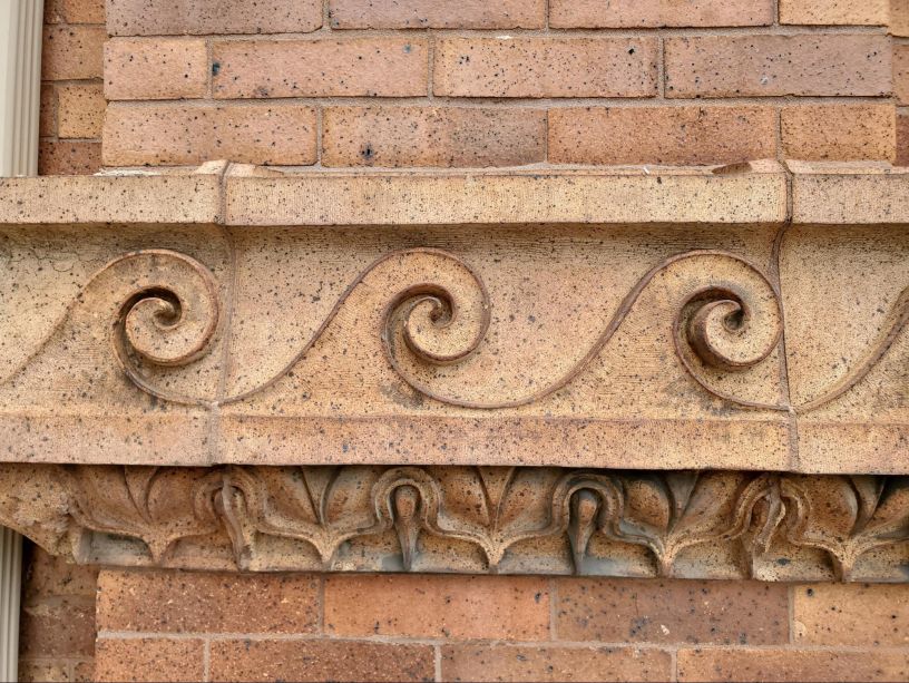
In last week’s article we took a look at an existing historic building with a light gray sandstone facade. The frieze at the top of the ground level showed signs of excessive water entry, deterioration, and discoloration. A link to that blog follows for reference: Vitruvian Waves and Architectural Friezes – PART I This week, we’re taking a look at a very similar issue at a different building, also built with a Vitruvian Wave frieze at the top of the ground floor. The picture below shows a portion of the front facade of a historic building. This building is built with iron spot brick. The frieze is also built with very similar source clay, but the frieze itself is produced through a chiseling process, not a terracotta process relief.
This particular relief is relatively deep, deeper than the particular Vitruvian Wave shown in our past article, in this series; however the stone is actually carved, not cast. Distinctions between carved masonry and cast materialsSimilar to terracotta masonry, this particular repeating pattern has exquisite detail. Sometimes terracotta and hand carved stone or carved kiln fired clay masonry have a very similar appearance, but looking closely you can see a few telltale distinctions:
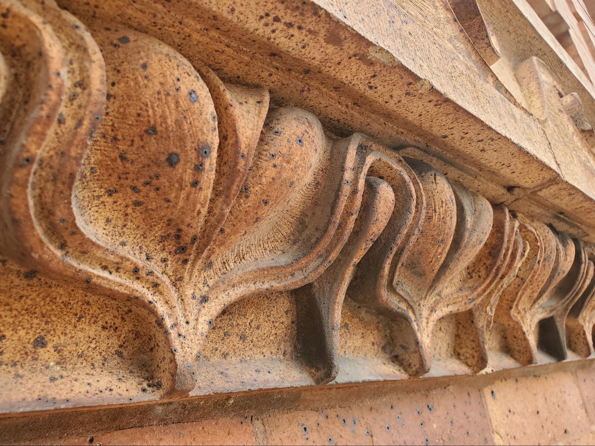
The design below the Vitruvian wave is called a lamb’s tongue, a repeating pattern, like a Greek Key, but with greater detail in this smaller area. A design, called a lamb’s tongue, is used in all different types of historic construction details. One of the most common is mild steel handrail finials. It’s clear though that the picture of a lamb’s tongue is not really accurate, instead it’s just a name that the entire classification of moldings are given because some of this style or classification do resemble a pedal or tongue. Other common elements, in plaster moldings, terracotta, cast iron, and stone carving follow:
At the right side of the picture below there is a dislodged joint between the individual masonry units of the frieze. When we think of stone or masonry sill, copings, plinths, and other types of masonry accent pieces (accent here meaning all of the masonry units which are not part of the central field of brick units in the wall), we tend to not think of them as masonry units. Granted in many cases metal work such as lead, tin, or even ferrous metals were historically used for cornices and other facade accents, but this building is an example of a case where the majority of facade accents are made from masonry very similar to typical brickwork. This type of masonry also needs preservation, restoration, maintenance and upkeep, just like field brickwork which requires tuck pointing and repointing.
The Vitruvian wave is also described as resembling a loosely rolled parchment scroll because in historic times, parchment or paper that was used was kept in rolls instead of being bound in a book.
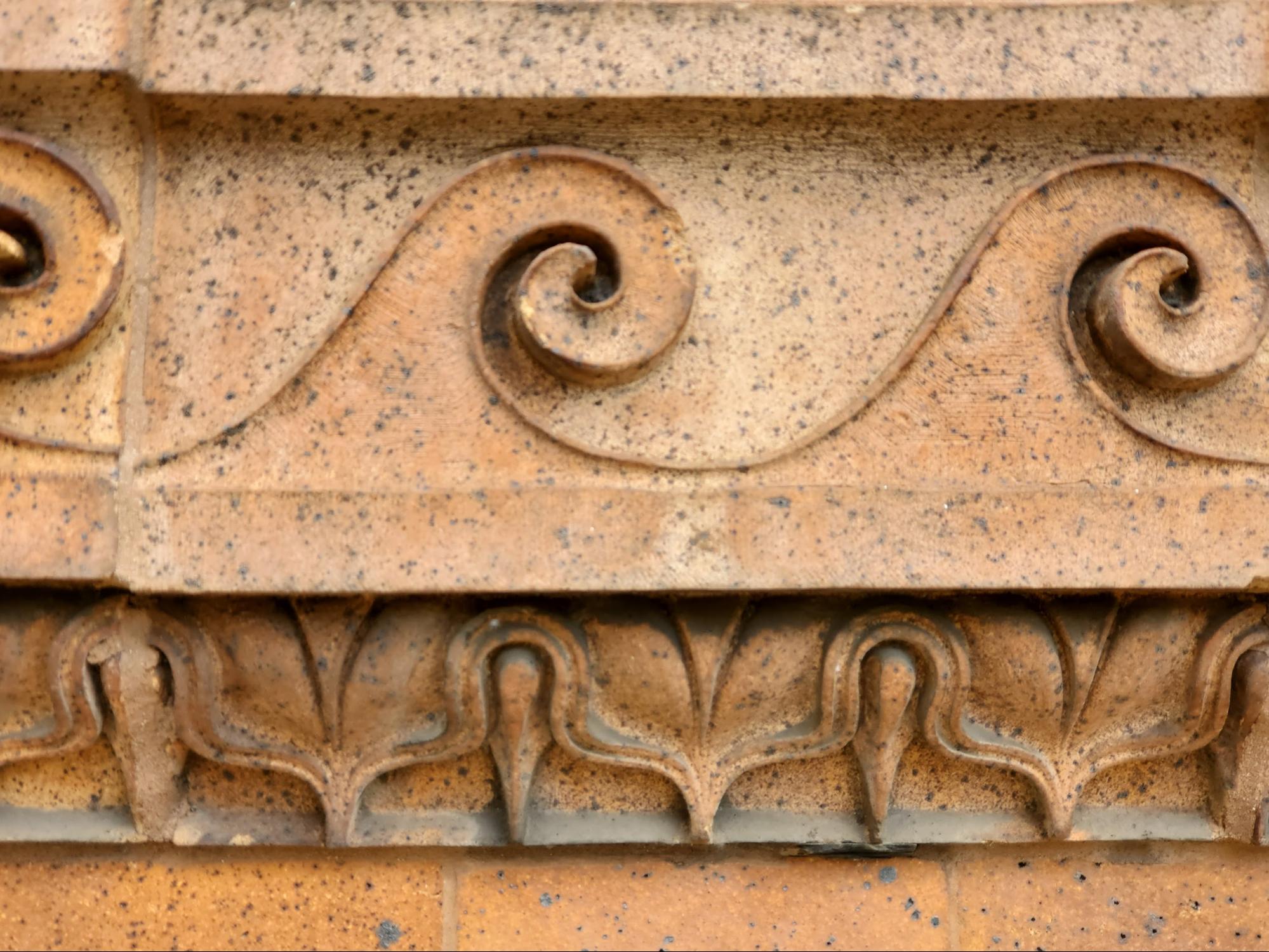
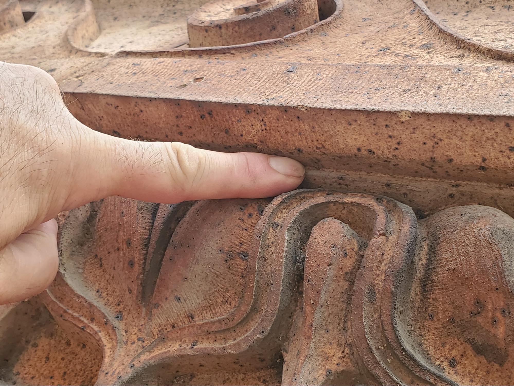
In a section above we describe the lamb’s tongue detail of the molding below the Vitruvian Wave. A close up of that carved masonry detail follows below. When looking closely at the detail you can see the high level of relief between the details of the carving. When you look closely at the surface of the masonry, you can also see A smattering of black spots all over the surface. Those black spots are often referred to as iron spots. We see these same spots in some types of light color brick work. Some types of brick clay have higher levels of calcium and lower levels of iron, but iron is still found in some of these high calcium bricks but in larger pieces or chunks which later oxidize at the surface and leave a black spot at each individual occurrence. Just below the outermost edge of the horizontal, linear, protruding edge of the frieze, you can see a line, cut into the masonry. This line creates a recess, very similar to a drip edge. A drip edge, the type that we most commonly see in building construction is made of galvanized steel or aluminum. In most cases the aluminum will be coated from the factory with a color paint to match the accent details of the building or will be precoated in a TPO or similar material for adhesion at the termination of the roof system at the top of the building facade. In this case, though, the masonry shelf created by the frieze has a relief cut to allow water to trip off the protruding masonry unit without running back to the lower masonry facade. This subtle and small details significantly helps preserve the facade by minimizing hydration during typical rainfall periods.
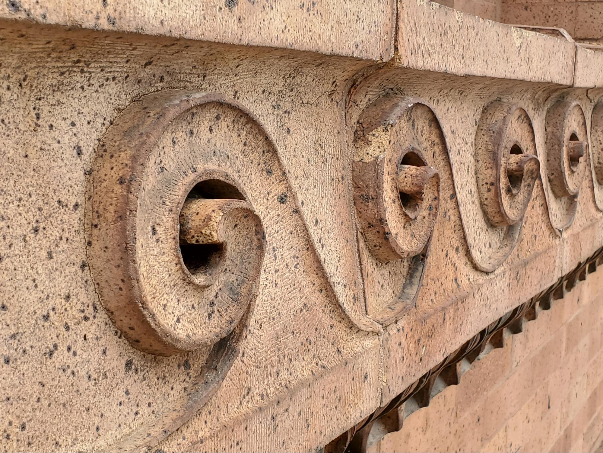
A kerf at a sillThis particular freeze is not a sill, but common to a sill or similar to a sill this particular projecting edge of the frieze has a kerf or relief cut at the underside of the outermost edge. That kerf along the bottom of the protruding element allows the outermost edge to be slightly lower than the portion just inside of the outermost edge of the projection. This detail is important in reducing the harmful effects of typical non wind-driven rain or precipitation. Wind-driven rain may still saturate the face of the building below the frieze, but in most cases of precipitation is not driven by rain, the raindrops will fall in a somewhat vertical pathway. The area of the facade below the projection will in most of those cases stay relatively dry. Staying relatively dry in the majority of precipitation events helps the masonry last much longer than it otherwise would if it were hydrated significantly at each successive rainfall event. Unlike a regular kerf, this projecting edge is actually cut at a chamfer, a slightly angled recess. That angled chamfer also helps prevent the masonry unit from planar fracture in the future. This type of element isn’t just found in hand carved friezes or the high end of preservation and masonry construction. Even linear sills or headers with significant projections often have a relief or curve installed inside of the outer edge at the underside of the horizontal masonry element.
Back in early 2023, our company took a close look at a building with a similar detail: kerfs that ran underneath the outer edge of a set of window sills at a historic masonry facade. You can take a look at details of That article at the link below: Water Conveyance And Facade Leakage
The picture below shows the kerf or chamfer recess, very clearly, at this masonry frieze. As a drop of water runs down a vertical face of a building it will have a tendency to return back towards a lower portion of the facade of the building, running horizontally. However, in this case when each drop of water runs back to the lower face of the building the drop of water will drop off of the horizontal projection when it reaches the returning vertical angle of the kerf or chamfer. This will keep the lower portion of the building dry during rains without high winds.
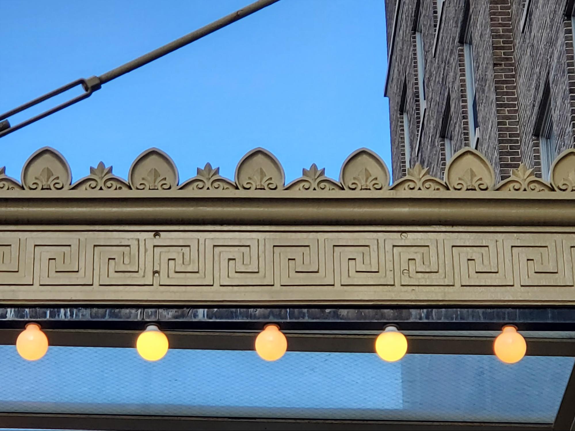
A rectilinear alternative Vitruvian waveAnother repeating pattern from Greek architecture is shown in the next picture below. This element is very similar to the Vitruvian wave, and also referred to as a scroll pattern or Greek Key, just like the Vitruvian Wave, this pattern repeats without variation and is often used in friezes and patterns or designs in classical or neoclassical architecture. This particular design is found at the sides of a porte cochere, larger than at typical portico, at a grand hotel entrance. The glass panel entrance roofs are common to allow passengers of vehicles to enter from the vehicle directly to the interior lobby in a rainstorm without getting wet.
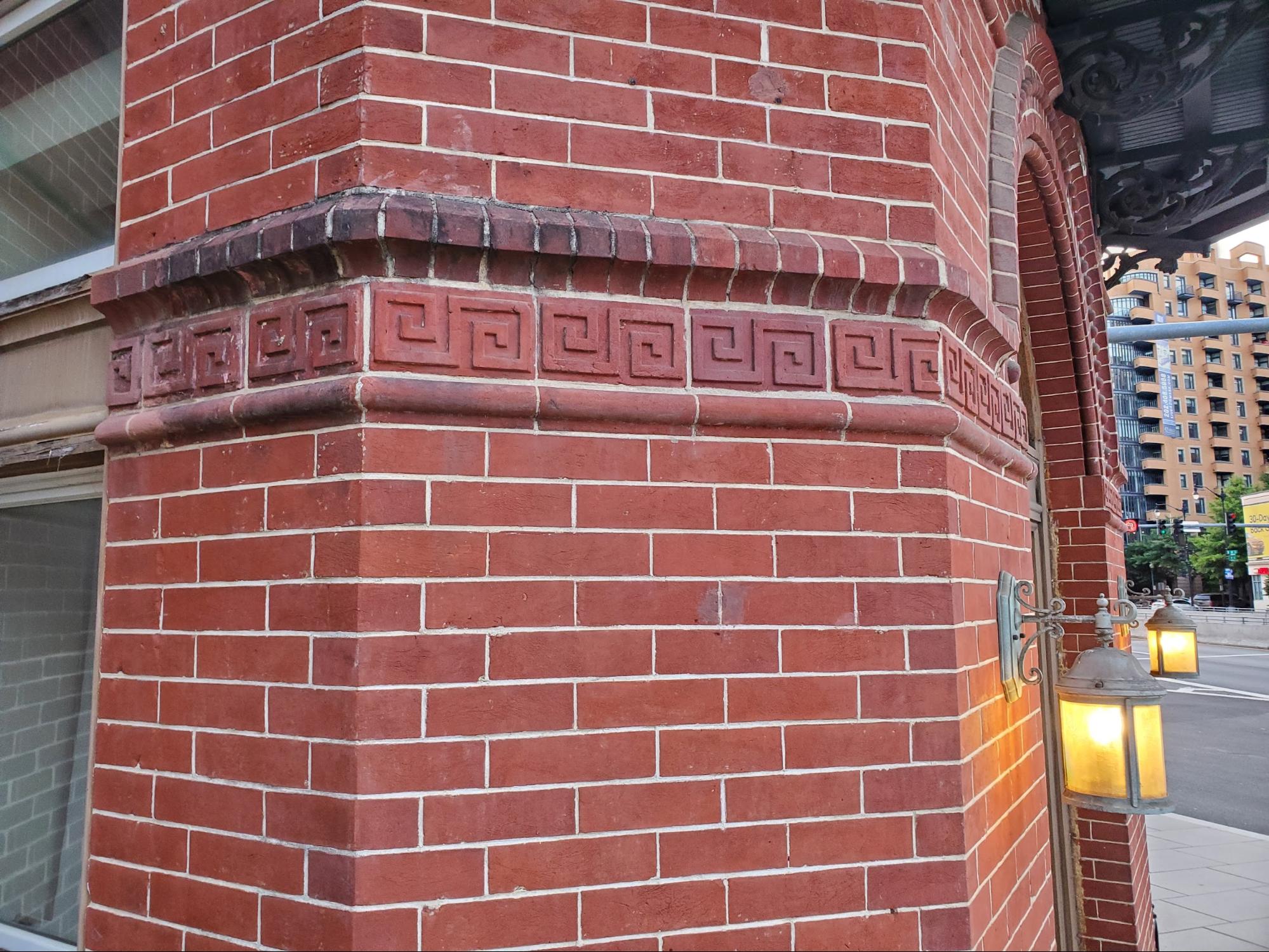
Here, in the next picture below, the same symbol is found at a freeze of terracotta clay tile, found in a accent at a facade of a building in Washington DC.
The scroll pattern terracotta sits above a stretcher course of hinge bricks and below a rowlock course of water table brick. Unlike the porte chocere pattern though, this one, below, has a 90-degree turn variation between each scroll, per pair. This is a rectilinear alternative to the Vitruvian wave.
In an upcoming article we will look at the functional engineering benefit of protecting architectural masonry facades. We talked about the direction of water, away from the building at ledges and projections at the facade, but in an upcoming article we will look closely at examples where projections have failed or have been built without an extending edge leading to water saturating and permeating into the masonry causing damage and bioconization which leads to failure of the masonry facade and accelerated deterioration. Historic masonry upkeep and preservationTo properly maintain, repair, and care for these historic buildings, a knowledge, interest and understanding of historic building principles is required. Here in Washington DC, historic masonry buildings are extremely expensive and the amount of financial loss caused by improper repointing and low quality construction is staggering. However, in addition to the direct financial value of the property, there is also a cultural loss when historic buildings are damaged. By comparison, consider neighboring poor cities, when historic buildings are damaged, it’s not just the loss of value to the property owner, there’s also a loss to all inhabitants and visitors of a city, present and future, who care about architecture, history, and culture. We encourage all of our clients, and all readers of this article and to our blog in general, to prioritize the historic built environment of Washington DC and neighborhoods such as Capitol Hill, Dupont Circle, and Georgetown and become educated on on the difference between proper historic preservation versus improper work which leads to significant damage to the historic fabric of a building. From a conservation and preservation perspective, several approaches can be taken to improve conditions related to deteriorated historic brick masonry. Primarily, lime mortar brick joints and low temperature fired soft red clay bricks should be inspected and checked on a routine maintenance schedule, either seasonally or at least annually. If brick masonry is kept in good condition, the life of embedded wood elements can be significantly extended. Hire a professional contractor which specializes, understands and appreciates historic construction elements and buildings. You can learn a lot more on our blog. Feel free to check it out. If you have questions about the historic masonry of your building in Washington DC, fill out the webform below and drop us a line. We will be in touch if we can help. <p>The post Vitruvian Waves and Architectural Friezes – PART II first appeared on Infinity Design Solutions.</p> Via https://www.ids-dmv.com/masonry/vitruvian-waves-and-architectural-friezes-part-ii/ What Are Vitruvian Waves And Why Should You Care?Today’s discussion is part of a 3-part series, the series goes into detail about architectural friezes, Vitruvian waves, historical significance and the importance of these details from a functional perspective. The outline of the articles in this series follows below:
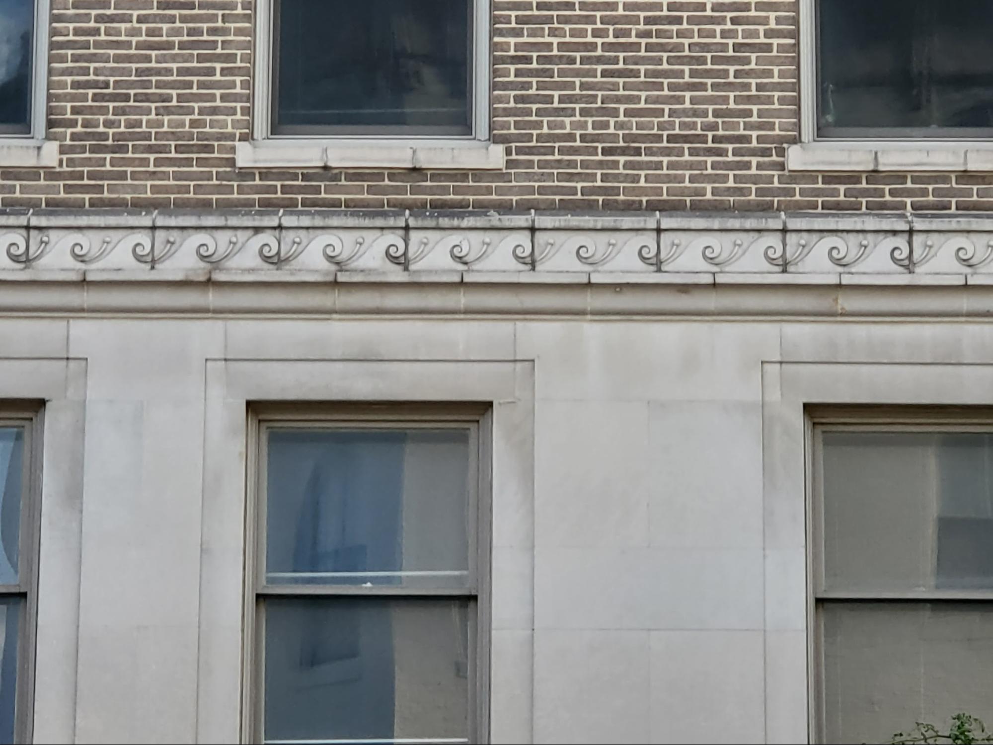
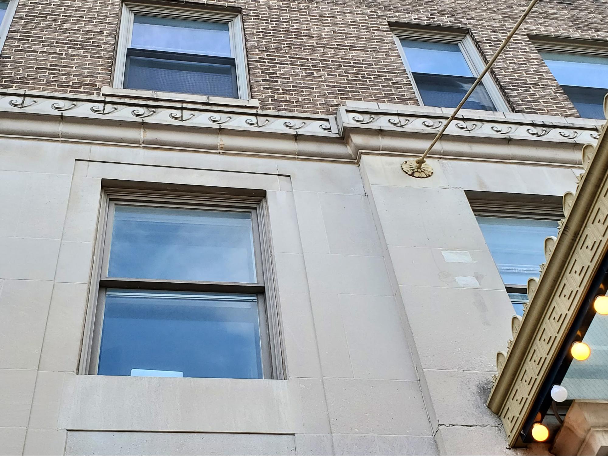
An architectural frieze is basically a masonry or similar type material band that runs horizontally across or around the facade of a building. Our articles are often focused on the principles of historic masonry restoration, preservation, tuckpointing or repointing, and preventative maintenance. Today though we’re going to discuss some classic architectural details of incredible craftsmanship and beauty. These details relate to the principles of building science that tie right back to the common brick used in the majority of brick buildings right here throughout Capitol Hill and the historic neighborhoods of Washington, DC. We’ve looked at many masonry buildings in the past with similar details. Today though, we’re taking a close look at a commonly used pattern that goes all the way back to Greek architecture. In addition to the aesthetic value, the symbolism, and the implications around quality and craftsmanship, there’s also a functional purpose to banding, horizontal friezes, and similar projecting elements in masonry facades. The history of architectural friezesFriezes in buildings go back to Greek and Roman architecture, also referred to as Greco-Roman architecture, from over 2,000 years ago. However, you can see examples of decorative headers above columns in Egyptian architecture that predates the vast majority of Greco-Roman architecture by thousands of years. The big difference between this type of Egyptian architecture and Greco-Roman architecture is that the Greco-Roman architecture is broken down into divisions, known as orders, within each entablature assembly, even in cases of varying design. While it may be true that the Greco-Roman approach to the order of entablature was designated and defined or restricted, it’s debatable whether they were the first to use architectural friezes. Evidence indicates carved and decorative banding above columns in horizontal arrays were created thousands of years before the Parthenon, for example which was being built about 2,500 years ago. The picture below shows a portion of the front facade of a historic masonry building. The lower level of the building is clad with a limestone or sandstone, carved with reliefs at each window opening, resembling contemporary casings, but recessed instead of applied and rectilinear as opposed to ornate. Greco-Roman classical orders of architecture included an architrave below the frieze and a cornice above the frieze. Here there is a stone detail below the frieze but no cornice above the frieze. Greco-Roman friezes were part of entablature assemblies that rested upon the columns. Often the columns would be set with the entablature above and then in a tympanum on top of the entablature . Today we might refer to the tympanum as a gable, in contemporary types of construction. The brick above the ribbon or frieze above the ground level is a common brick, not a pressed brick. Accordingly, this type of brick has a relatively thick motor joint. The brickwork is built with a common bond. The common bond is not related specifically to the common brick, in fact it would be almost just as typical to see common brick Built-in a running bond but in this case the common brick is built with a common bond. The upper window sills are a limestone, matching the facade cladding at the level below.
Use of architectural friezes in the New WorldWashington DC is very interesting, in terms of architecture. DC is one of the relatively early cities on the Eastern seaboard of the United States, part of the original 13 colonies of America. But not nearly as old as other nearby cities such as New York, Philadelphia, and Baltimore. Many of the large buildings in Washington DC were designed and built at a period of time after the Baroque or Rococo styles of architecture. Commonly, in architectural trends, successive styles are a reaction or revolt to the prior style. Although neoclassical architecture has relatively simple designs in terms of rectilinear forms, the grand scale and particularly the entablature and orders of details related to the architectural friezes, architraves, and cornices, are borrowed from classical architecture. When you look at the side of the portico, (which we will talk about in much greater detail in next week’s continuation article), you may notice a similar but different symbol that runs around the horizontal band at the edge of the awning.
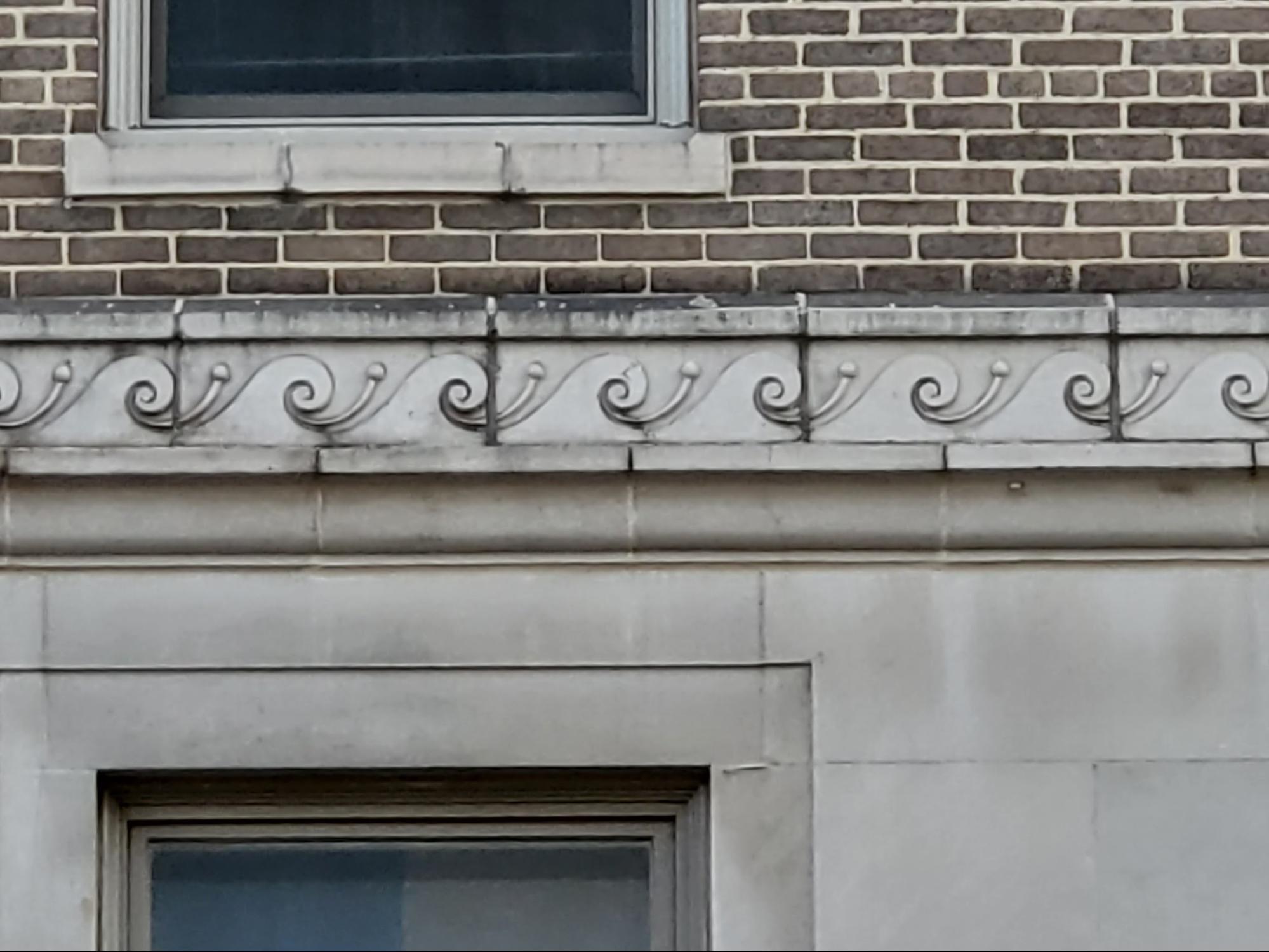
The Vitruvian WaveThe Vitruvian wave is also known as a running dog pattern. However, the one seen in this particular photo clearly resembles what we think of today as a nautical breaking wave, not a running dog, and this symbol has a few different potential deeper meanings. Much of this discussion is based around the architectural details of this type of historic construction, but some of the elements that our company focuses most on are related to preservation, upkeep, maintenance, and restoration. When you look close in the picture below you can see there is a darker area on top of a limestone frieze banding. That darker area is at a relatively horizontal section of the banding which sort of creates a shelf. There’s a grade to that almost horizontal area which allows water to drain away from the facade. It also helps keep the lower portions of the wall dryer in rain events that are not coincident with heavy winds. Heavy winds change the way precipitation will wet a building facade. But in many cases the larger portion of the facade below is protected by this slate projection of the band area. When you look closely though, you can see that there is deterioration at the masonry at the top of the frieze band and also deep recesses in the mortar joints between the individual sections of the limestone. This type of slow but pervasive damage can be mitigated by routine maintenance. This type of maintenance doesn’t have to happen every day and it’s not even expensive but it needs to have a engaged and conscientious masonry contractor to provide careful seasonal cleaning and restoration of the mortar joints. The mortar joints may be able to last many years between each repointing.
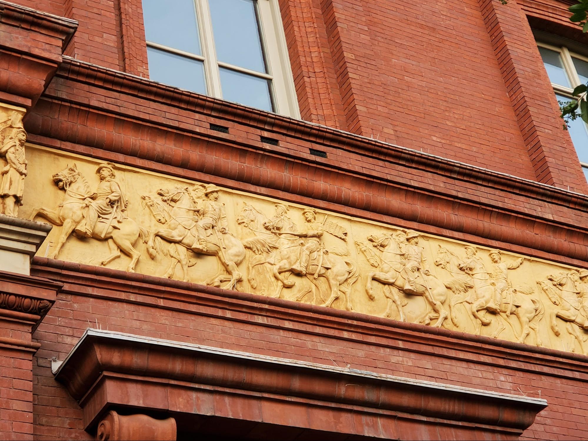
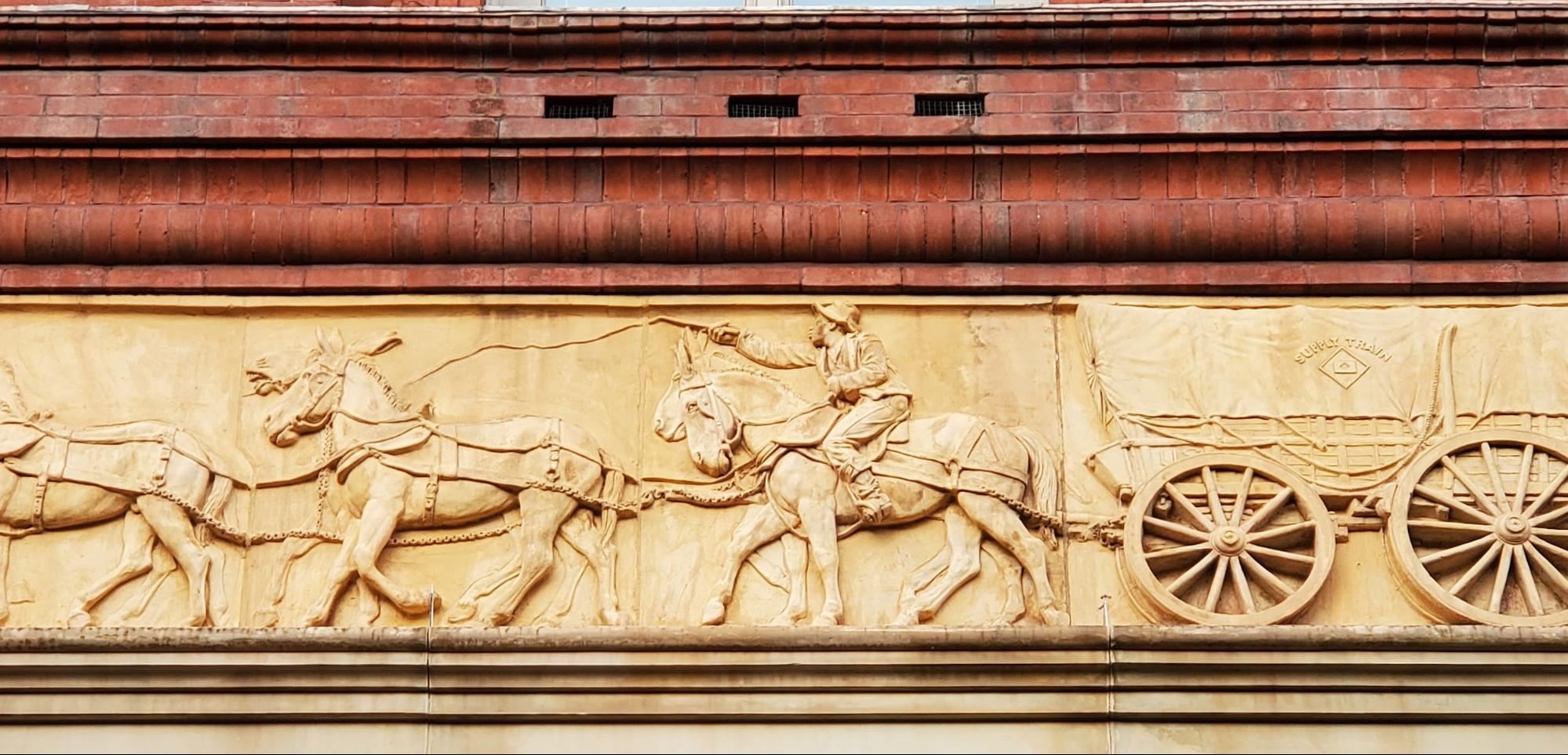
A noteworthy American reliefAlthough there are clearly deep ancient historic origins of architectural friezes, America of course has also put its own spin on this design detail. The frieze at the Greek parthenon is one of the most noteworthy in the world, that particular architectural frieze is over 3′ tall and over 500′ in length. By comparison the architectural frieze at the National Building Museum, in Washington DC, is approximately 3′ high by over 1000′ in length. The architect may not have been trying to compete, but an enormous effort has been applied into the design and construction this particular architectural detail.
This particular detail was built into the building prior to the finalization of construction in the late 1800s. At the time, surely, the impact of the still Civil War was still palpable and present. The artwork in the casting of this particular frieze included the imagery of soldiers, calvary, wagons, and even depictions of sailors pulling boats and infantrymen driving artillery. While earlier historic friezes were often stone carved, this particular frieze was made from cast terracotta. These details make more sense when you consider the original use of the building. Currently the building museum is dedicated to highlight elements of architecture, engineering, and construction and related history and technology. At the time of original construction though this was a military pension building where the administration of pensions or retirement funds for military personnel was managed and dispensed. The level of architecture and detail in construction was enormous, compared to the amount of effort put into similar buildings today. The building museum’s website (at https://www.nbm.org/about/historic-home/) states that the original construction cost was $886,614. This factoid is fascinating. That value is similar to the cost of construction for the simplest of contemporary homes, today. That money, in 1894, would be worth a lot more today, because of typical inflation over the last roughly 127 years. Google says that $1 in 1894 would be worth about $353.63 in today’s money. It’s hard to believe. That means a penny would be worth $3.54. The implications, though, are fascinating. The value of the original cost of construction is a total of roughly $32 million in today’s dollars, adjusting for inflation. Part of the reason that this is fascinating though is not about the difference of dollars, through inflation, between 1894 and 2023, today. The real story is in the difference in those values of what that adjusted value purchased back then, in terms of construction, and what can be bought today. The cost of constructing this building today would cost 10 times more than it cost back then, even after adjusting for inflation. That’s an astounding revelation. As a side note, the level of fine detail in the relief is almost unparalleled with typical stone carvings; however, the downside or tradeoff with terracotta is long term durability. Clearly though after 100 years of exposure to the elements this particular relief shows near no signs of deterioration, either through durability or impeccable restoration and preservation.
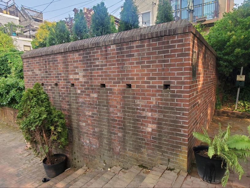
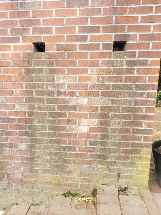
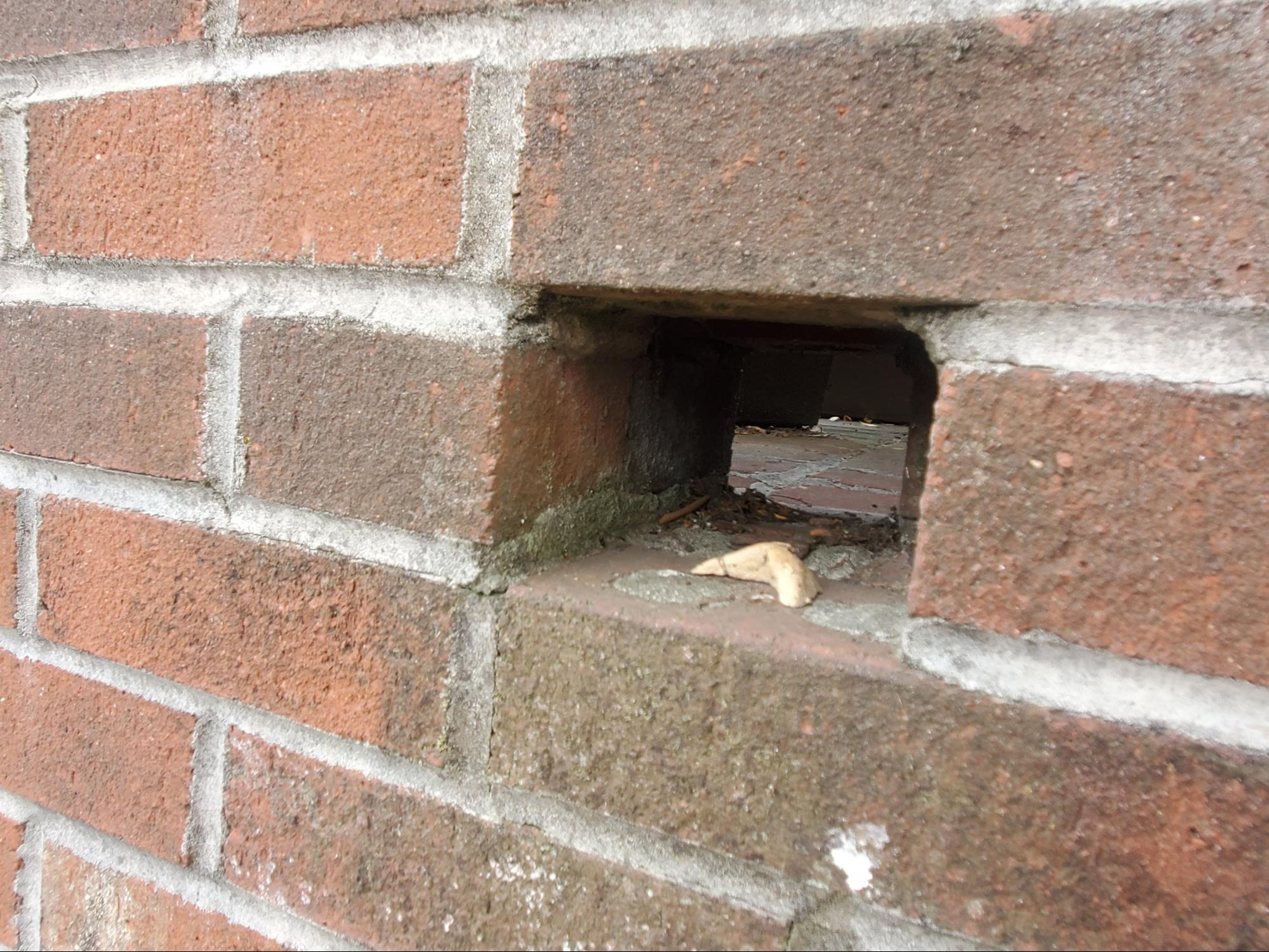
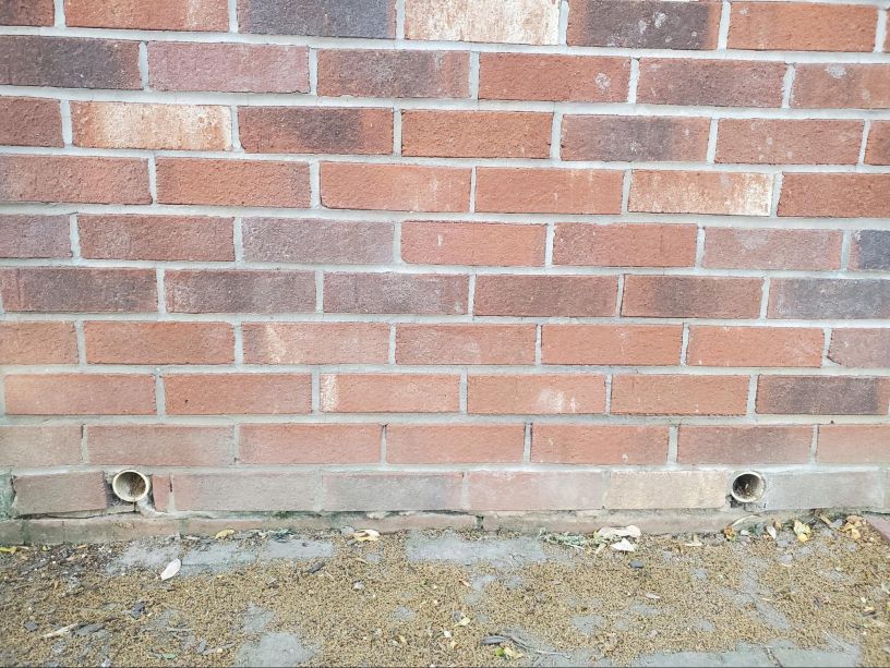
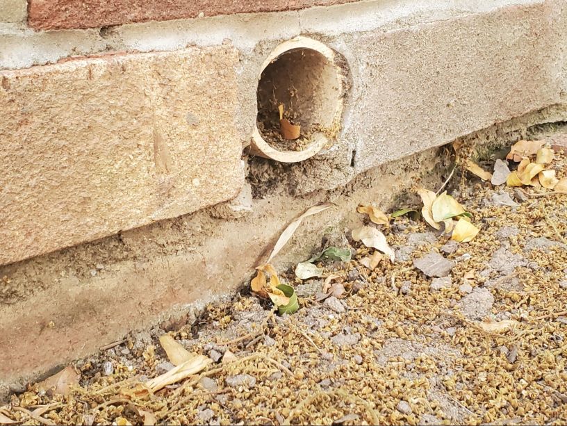
Historic masonry upkeep and preservationOn the surface, these types of ornate and high class details seem different than the average Washington DC residential or even more contemporary commercial building, However, some of the elements have significant consistencies. Even in the historic rowhomes of Capitol Hill, we have brick buildings with terracotta inlays. The inlays have three dimensional details, just like a carved relief from historic times but they are there in the front of facades, on the busy streets of our Washington DC neighborhoods. In a forthcoming week, we will post part two of this fascinating series on architectural facade details and historic architecture. . To properly maintain, repair, and care for these historic buildings, a knowledge, interest and understanding of historic building principles is required. Here in Washington DC, historic masonry buildings are extremely expensive and the amount of financial loss caused by improper repointing and low quality construction is staggering. However, in addition to the direct financial value of the property, there is also a cultural loss when historic buildings are damaged. By comparison, consider neighboring poor cities, when historic buildings are damaged, it’s not just the loss of value to the property owner, there’s also a loss to all inhabitants and visitors of a city, present and future, who care about architecture, history, and culture. We encourage all of our clients, and all readers of this article and to our blog in general, to prioritize the historic built environment of Washington DC and neighborhoods such as Capitol Hill, Dupont Circle, and Georgetown and become educated on on the difference between proper historic preservation versus improper work which leads to significant damage to the historic fabric of a building. From a conservation and preservation perspective, several approaches can be taken to improve conditions related to deteriorated historic brick masonry. Primarily, lime mortar brick joints and low temperature fired soft red clay bricks should be inspected and checked on a routine maintenance schedule, either seasonally or at least annually. If brick masonry is kept in good condition, the life of embedded wood elements can be significantly extended. Hire a professional contractor which specializes, understands and appreciates historic construction elements and buildings. You can learn a lot more on our blog. Feel free to check it out. If you have questions about the historic masonry of your building in Washington DC, fill out the webform below and drop us a line. We will be in touch if we can help. <p>The post Vitruvian Waves and Architectural Friezes – PART I first appeared on Infinity Design Solutions.</p> Via https://www.ids-dmv.com/masonry/vitruvian-waves-and-architectural-friezes-part-i/ What is the Purpose of a Scrupper?The pictures below show an example of a patio kneewall with holes at the base of the patio area. The holes in the brick wall are scuppers. Today we will look at the following topics: |

About UsInfinity Design Solutions LLC (IDS) is a full service general contracting company in the heart of the Dupont Circle neighborhood of Washington, DC. We focus on repair and renovation of buildings and facilities in both historic designated neighborhoods and the commercial-zoned central business district of the city. Follow Us
|